AI technical title is built by Patsnap AI team. It summarizes the technical point description of the patent document.
a measuring method and high-precision technology, applied in the direction of analysing fluid analysing solids using ultrasonic/ultrasonic/infrasonic waves, ultrasonic/sonic/infrasonic waves, etc., can solve the problem of high cost of known techniques, the upper limit of the precision practically achievable by the technique, and the inability to achieve the precision of microns or fractions
Inactive Publication Date: 2006-07-25
NEXENSE
View PDF15 Cites 72 Cited by
Summary
Abstract
Description
Claims
Application Information
AI Technical Summary
This helps you quickly interpret patents by identifying the three key elements:
Problems solved by technology
Method used
Benefits of technology
Problems solved by technology
As brought out in U.S. Pat. No. 6,621,278, many measuring techniques are known for measuring distance, temperature, and other parameters, but such known techniques generally increase in expense according to the precision desired, and also generally have an upper limit as to the precision practically attainable by the technique.
For example, the measurement of distances of meters or kilometers with a precision of microns or fractions of a micron is extremely expensive, if attainable at all.
The same limitations apply with respect to measuring temperature, force, and other conditions.
Method used
Image
Click on the blue label to locate the original text in one second.
Reading with bidirectional positioning of images and text.
Examples
Embodiment Construction
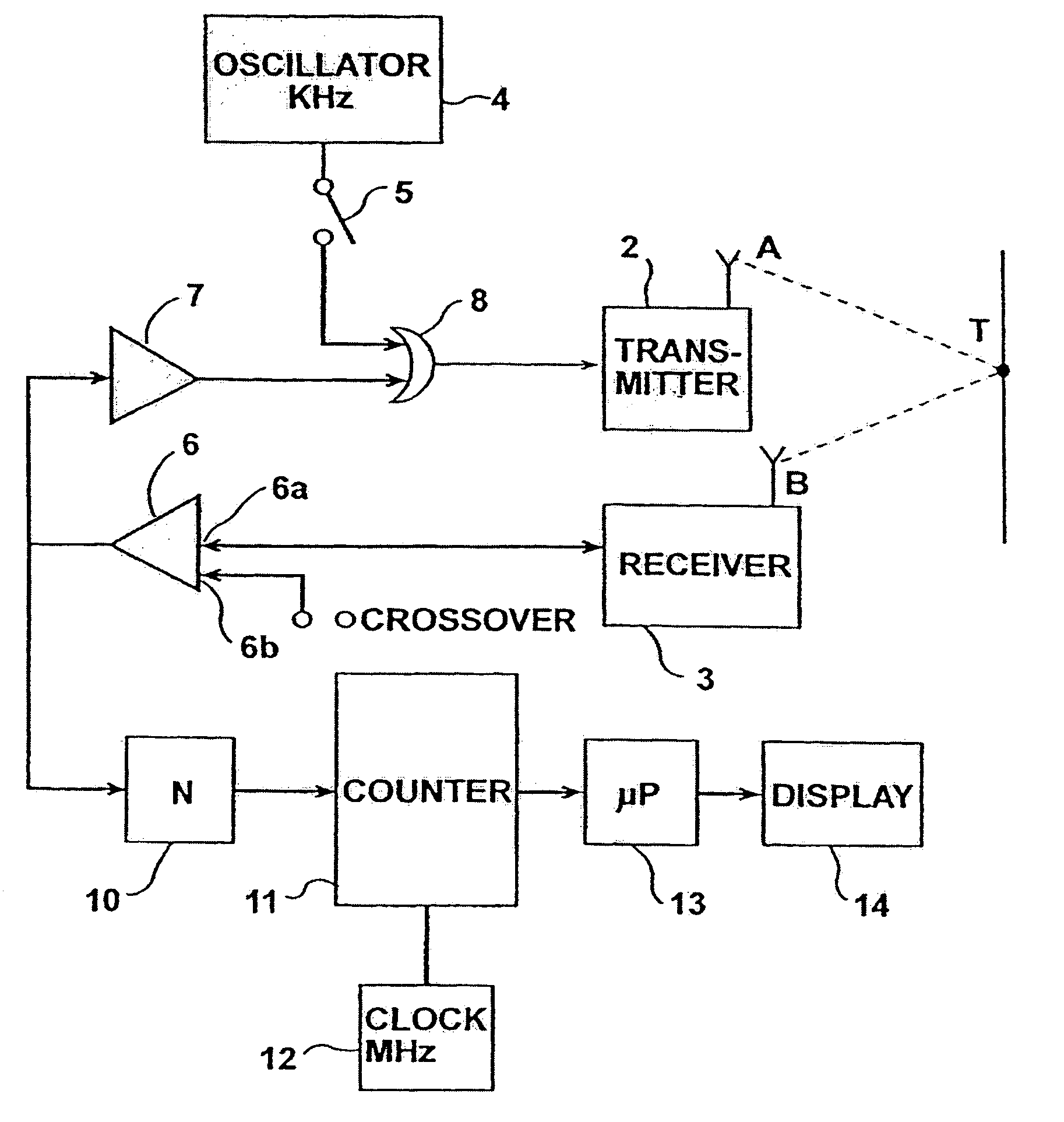
[0024]FIG. 1 is a block diagram illustrating a system for precisely measuring the distance to point T of a target or other object. The illustrated system is an echo system, and therefore the distance to target T is measured by measuring the transit time taken by a cyclically-repeating energy wave transmitted at point A towards the target T until its echo is received at point B. The distance ATB thus constitutes the transmission channel between locations A and B.
[0025]The system illustrated in FIG. 1 thus includes a transmitter 2 at location A for transmitting the cyclically-repeating energy wave towards target T, and a receiver 3 at location B for receiving the echo of the cyclically-repeating energy wave after reflection from target T. Initially, the energy wave is continuously transmitted from an oscillator 4 under the control of a switch 5 until the echoes are received by receiver 3; once the echoes are received, switch 5 is opened so that the received echo signals are then used ...
PUM
Property
Measurement
Unit
wavelengths
aaaaa
aaaaa
transit distance
aaaaa
aaaaa
transit distance
aaaaa
aaaaa
Abstract
A method and apparatus for monitoring a condition having a known relation to, or influence on, the transit time of a cyclically-repeating energy wave moving through a transmission channel, by: (a) transmitting a cyclically-repeating energy wave through the transmission channel from a transmitter at one end to a receiver at the opposite end; (b) continuously changing the frequency of the transmitter according to changes in the monitored condition while maintaining the number of waves in the transmission channel as a whole integer; and (c) utilizing the changes in frequency of the transmitter to provide a continuous indication of the monitored condition. Operation (b) is preferably performed by detecting a predetermined fiducial point in each cyclically-repeating energy wave received by the receiver, but may also be performed by the use of a phase-locked loop circuit, to maintain the number of energy waves in the loop of the transmission channel as a whole integer.
Description
RELATED APPLICATIONS[0001]The present application is a Continuation-in-Part of U.S. patent application Ser. No. 10 / 615,952 filed Jul. 10, 2003, now U.S. Pat. No. 6,856,141, which in turn is a continuation of U.S. patent application Ser. No. 09 / 983,430 filed Oct. 24, 2001, now U.S. Pat. No. 6,621,278, issued Sep. 16, 2003, which in turn is a Continuation-in-Part of Application No. PCT / IL00 / 00241 filed Apr. 27, 2000, which claims priority from Israel Patent Application No. 129651 filed Apr. 28, 1999.FIELD AND BACKGROUND OF THE INVENTION[0002]The present invention relates to high precision measuring methods and apparatus, and particularly to a method and apparatus for measuring distance, temperature, and virtually any other parameter or condition having a known relation to, or influence on, the transit time of movement of an energy wave through a medium. The present invention is particularly useful in the method and apparatus described in the above cited U.S. Pat. No. 6,621,278, the co...
Claims
Application Information
Patent Timeline
Application Date:The date an application was filed.
Publication Date:The date a patent or application was officially published.
First Publication Date:The earliest publication date of a patent with the same application number.
Issue Date:Publication date of the patent grant document.
PCT Entry Date:The Entry date of PCT National Phase.
Estimated Expiry Date:The statutory expiry date of a patent right according to the Patent Law, and it is the longest term of protection that the patent right can achieve without the termination of the patent right due to other reasons(Term extension factor has been taken into account ).
Invalid Date:Actual expiry date is based on effective date or publication date of legal transaction data of invalid patent.

