Hand tool with impact drive and speed reducing mechanism

a technology of impact drive and speed reduction mechanism, which is applied in the direction of manufacturing tools, wrenches, portable drilling machines, etc., can solve the problems of failure to produce additional torque, hammers completely miss the anvil, and the tool is left unusable, so as to increase the driving force, and reduce the rotational speed of the motor

Active Publication Date: 2006-07-25
VESSEL FUKUCHIYAMA
View PDF22 Cites 57 Cited by
  • Summary
  • Abstract
  • Description
  • Claims
  • Application Information

AI Technical Summary

Benefits of technology

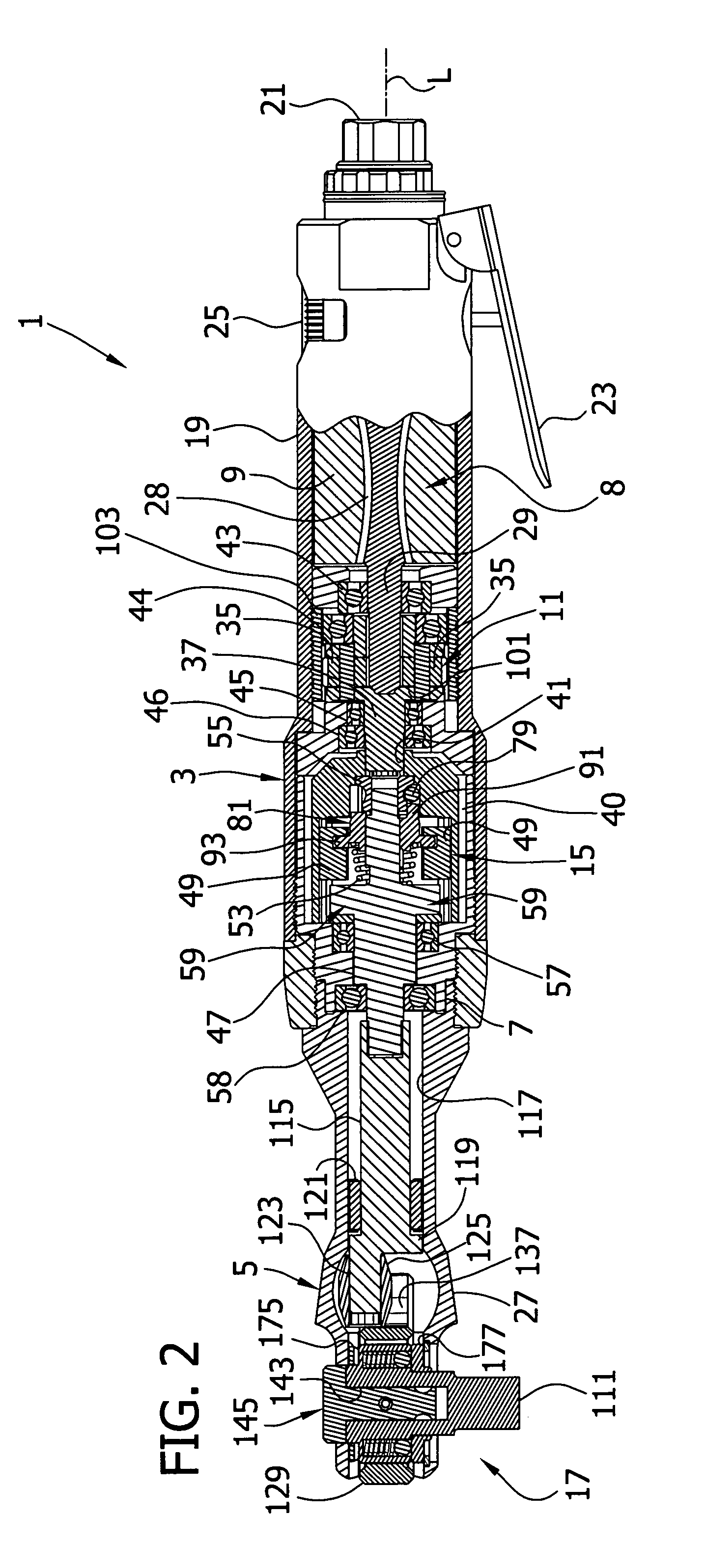
[0010]In another aspect of the invention, the tool comprises a housing with first and second longitudinal ends and a longitudinal axis. A head is attached to the housing toward the first longitudinal end for operatively engaging the mechanical fastener, and a motor and motor shaft are disposed in the housing toward the second longitudinal end for driving the head. The tool additionally comprises a planetary reducing gear between the motor and the head for reducing rotational speed of the motor transferred to the head. Planetary gears of the gear train receive the motor shaft of the motor and conjointly rotate therewith inside a sun gear, thus reducing the rotational speed of the motor. An impact drive is operatively provided between the planetary reduction gear and the head for selectively increasing the driving force to the head when necessary for tightening or loosening the mechanical fastener.

Problems solved by technology

However, because the impact drives of these tools generally operate at the same rate as the motor, they can prematurely wear out before other components of the tool and can possibly leave the tool unusable.
This often occurs so rapidly that the hammers impact the anvils before corresponding surfaces fully register, or alternatively the hammers completely miss the anvils and fail to produce any additional torque.
Moreover, when the frictional resistance of the fastener exceeds the additional torque produced by the hammers, the cam ball and impact clutch may unnecessarily push the hammers into repeated registration with the anvils before an operator can disengage the motor.
This can be hard on components of the impact drive (e.g., the cam ball and impact clutch) and may damage them or prematurely wear them out before other components of the wrench.
But as was previously described for the impact wrench of U.S. Pat. No. 4,821,611, the impact drive of this wrench operates at the same rotational speed as the motor and is susceptible to producing excess, unnecessary impacts that can prematurely wear out components of the drive.
However, these tools tend to be direct drive and do not have the advantages of a ratchet head.
Moreover, these tools may use externally connected gears that can be relatively large.
(For example, the speed reducing mechanism reduces breaking power on the motor generally caused by the high speed impacts delivered by the impact drive, which can result in lost lever force to the fastener.
The output of Van Laere's impact device directly drives the lug and does not obtain any additional mechanical advantage or speed reduction.

Method used


Image

  • Hand tool with impact drive and speed reducing mechanism
  • Hand tool with impact drive and speed reducing mechanism
  • Hand tool with impact drive and speed reducing mechanism

Examples


Embodiment Construction

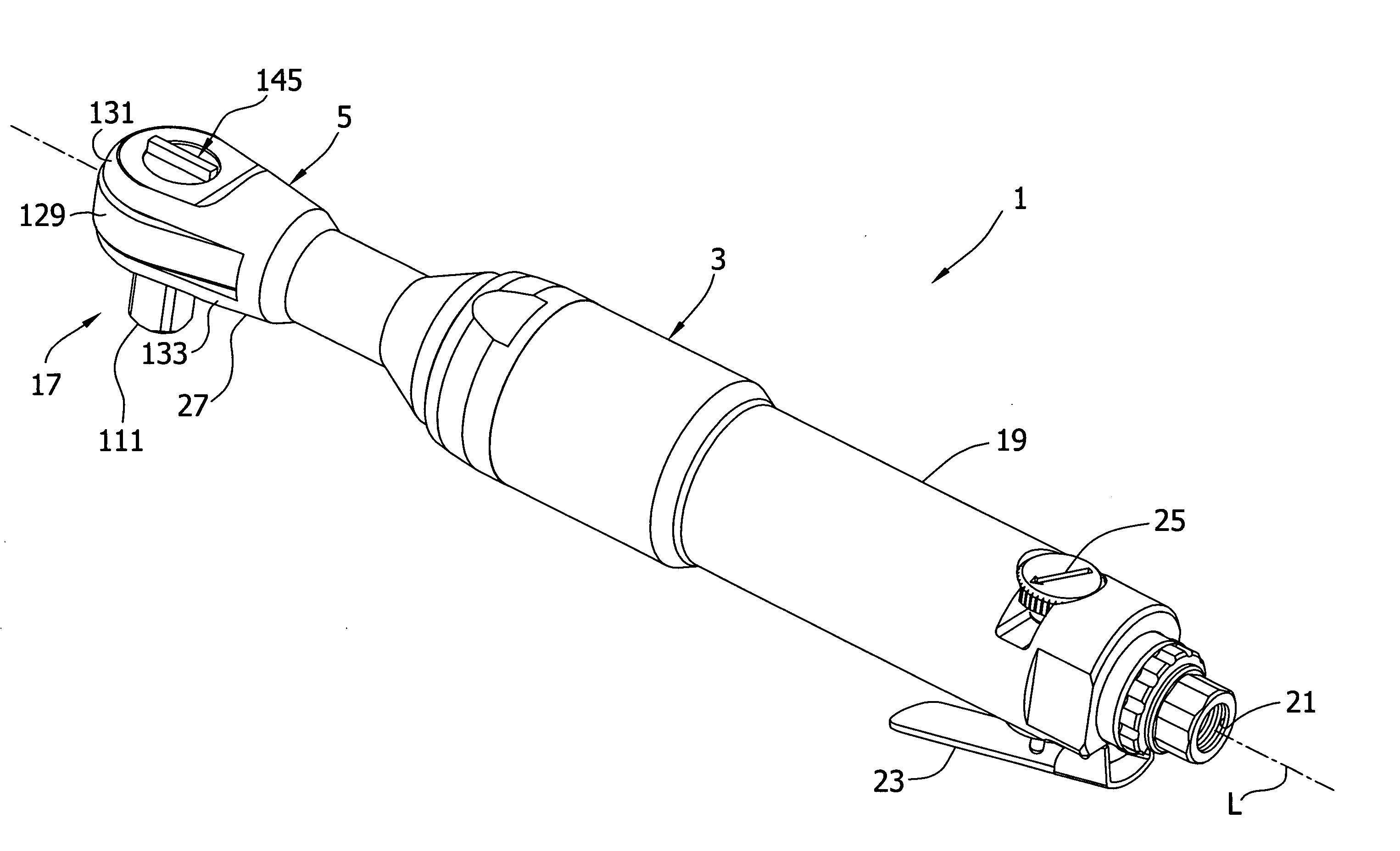
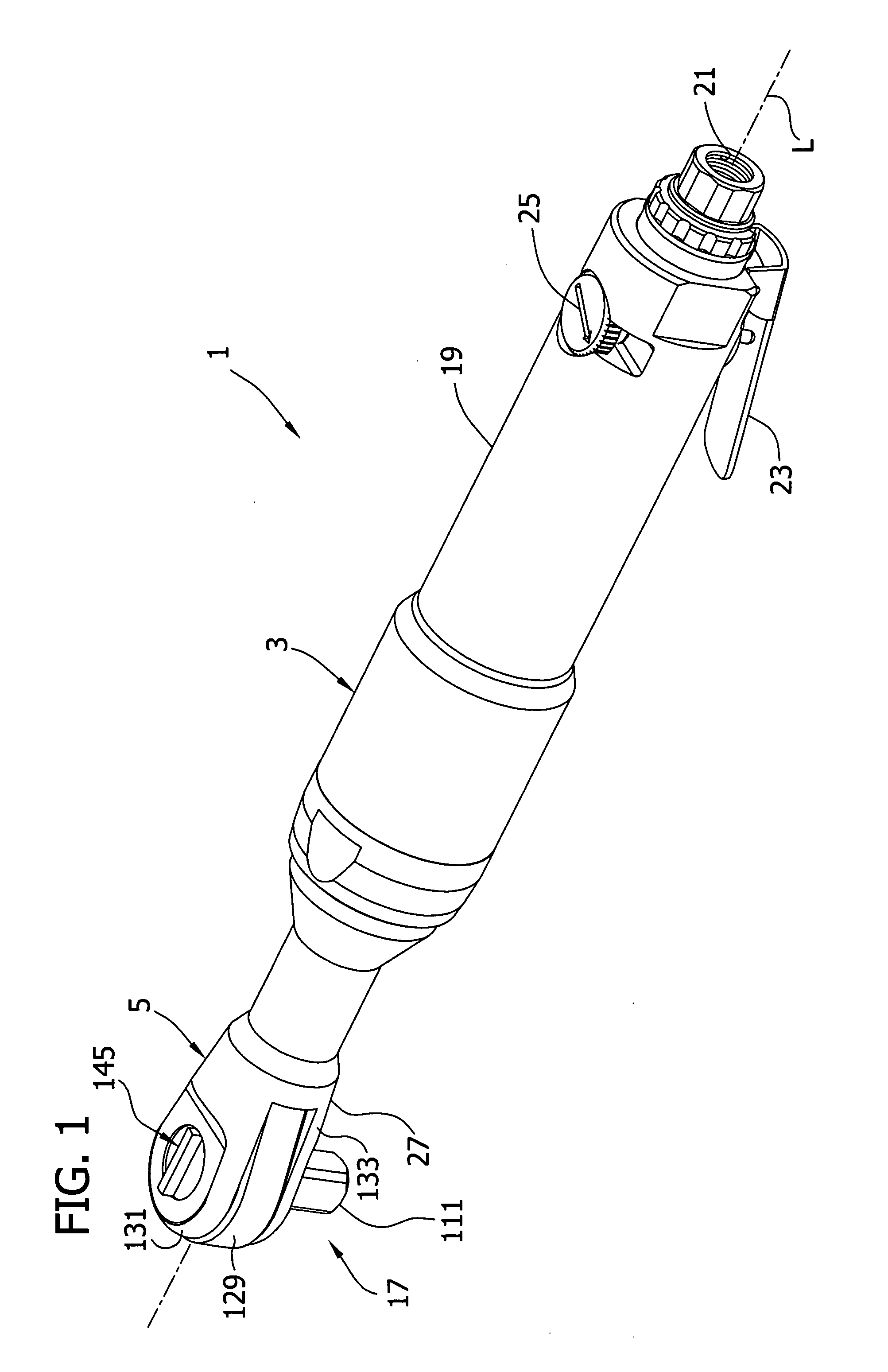
[0021]Referring now to the drawings, and particularly to FIGS. 1 and 2, a hand-held power driven ratchet wrench is generally indicated at reference numeral 1. The wrench 1 includes a tubular housing, shown generally at 3, and a head, indicated generally at 5. As shown in FIG. 2, the housing 3 and head 5 are connected by a threaded internal coupling 7 and securely encase the operative components of the wrench 1, including a motor, generally indicated at 8, having a rotor 9. The housing 3 also contains a planetary reduction gear 11, an impact drive 15, and a ratchet mechanism 17 (the reference numerals designating their subjects generally). Each of these components will be described in greater detail hereinafter. For convenience of description, when describing orientation of these components, the head 5 is understood to be located toward a forward end of the wrench 1 and the motor 8 toward a rearward end. The motor 8 illustrated and described herein is a standard air driven motor of t...


PUM

PropertyMeasurementUnit
speedaaaaaaaaaa
torqueaaaaaaaaaa
axis of rotationaaaaaaaaaa

Abstract

A power driven tool useful for tightening and loosening a mechanical fastener includes an impact mechanism. Preferably, the tool is pneumatic and includes a ratchet head and an impact device for providing additional torque to the ratchet head. A planetary reduction gear reduces the high output speed of a pneumatic motor for input into the impact device and reduces wear on the impact device.

Description

BACKGROUND OF THE INVENTION[0001]This invention relates generally to power driven tools, and more specifically it relates to a power driven tool for tightening or loosening fasteners and also having an impact drive and a speed reducing mechanism.[0002]Power driven tools for tightening or loosening fasteners (e.g., nuts and bolts) are known, and power driven tools incorporating impact drives that can intermittently provide an increased amount of torque for tightening or loosening fasteners are common. In a typical tool, a motor and motor shaft rotate an output shaft for turning the fastener. The impact drive is generally positioned between the motor shaft and output shaft to provide the increased torque as necessary. However, because the impact drives of these tools generally operate at the same rate as the motor, they can prematurely wear out before other components of the tool and can possibly leave the tool unusable.[0003]An impact wrench incorporating a ratchet head is disclosed ...

Claims


Application Information

Patent Timeline
Patent Type & Authority Patents(United States)
IPC IPC(8): B25B13/46B23B45/04B27C3/08
CPCB25B21/004B25B21/026B25B21/02
Inventor IZUMISAWA, OSAMU
Owner VESSEL FUKUCHIYAMA
Why Eureka
Try Eureka