Armor module

a technology of armor module and casing, applied in the field of armor modules, can solve the problems of significant shortness of the casing, insufficient ballistic length, and essentially horizontal gap between neighboring modules, and achieve the effect of increasing the durability of the casing

Inactive Publication Date: 2006-07-25
STATE OF ISRAEL MINIST OF AGRI & RURAL DEV AGRI RES ORG (A R O) (VOLCANI CENT)
View PDF33 Cites 27 Cited by
  • Summary
  • Abstract
  • Description
  • Claims
  • Application Information

AI Technical Summary

Benefits of technology

[0017]In accordance with one particular embodiment, the casing has a parallelogram section and by a modification thereof, the casing has a section of a parallelogram with one or both of an opposing top and a bottom edge, being truncated, for increasing durability of the casing.

Problems solved by technology

First, adjacent top and bottom edges of a housing, the cassettes are significantly short and do not provide sufficient ballistic length, i.e. effective minimal length of the cassettes required for efficiently destroying / stopping a charged-shape projectile.
A second disadvantage of the heretofore known modules is such that an essentially horizontal gap existing between neighboring modules when two modules are successively mounted on top of one another, accumulates to the end effect of an armor module.

Method used


Image

  • Armor module
  • Armor module
  • Armor module

Examples


Embodiment Construction

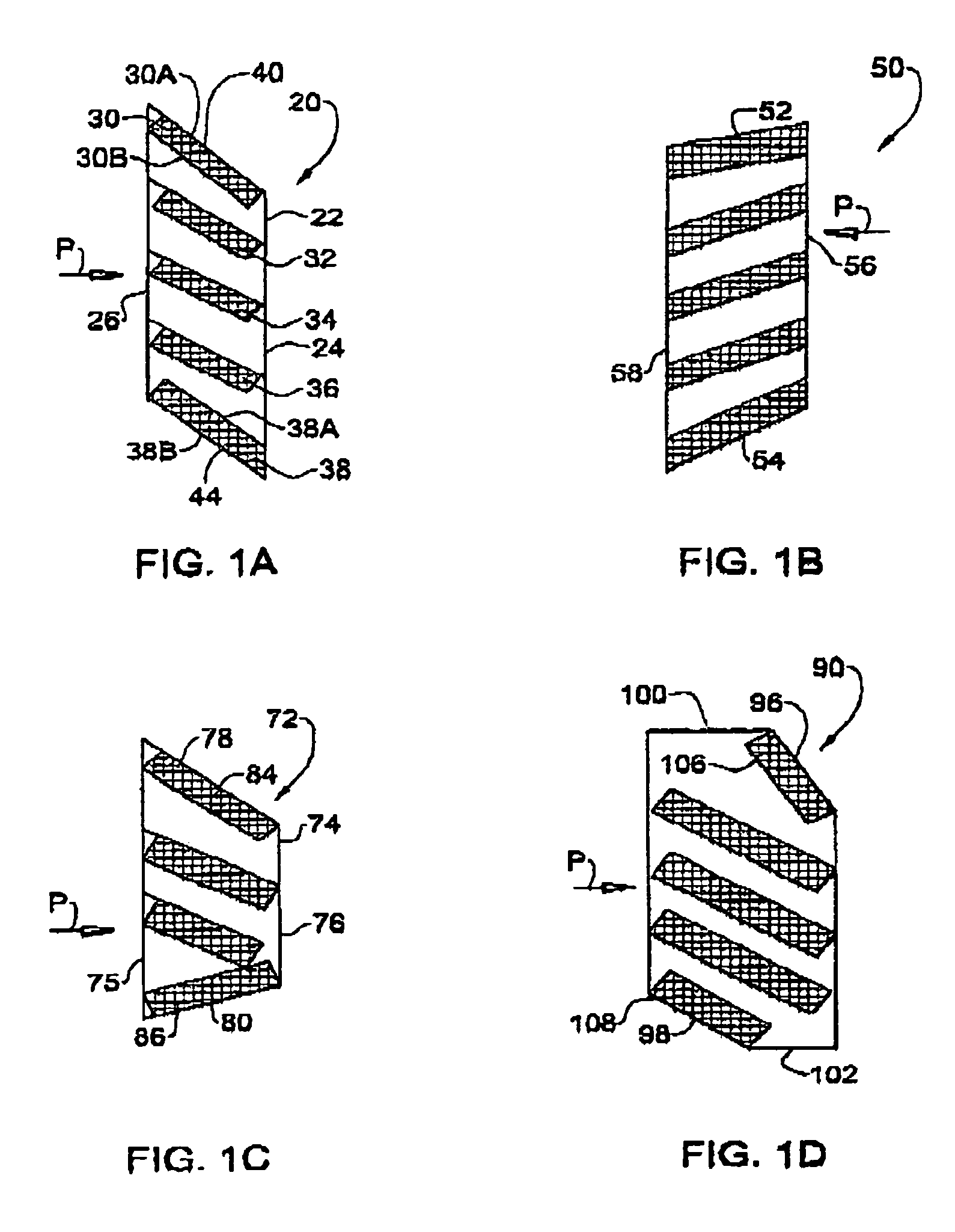
[0022]FIG. 1A illustrates a longitudinal section through an armor module in accordance with the present invention generally designated 20. The armor module comprises a casing 22 formed of a rigid material, say metal, or other durable material such as reinforced Kevlar™ or other composite material. The casing comprises a front face 26, a rear face 24, (the latter being an option) and a plurality of cassettes designated 30, 32, 34, 36 and 38.

[0023]As illustrated with reference to topmost and bottom most cassettes 30 and 38 respectively, each of the cassettes comprises a top base plate designated with the respective number of the cassette and an indication A and a bottom base plate indicated with a B, both plates being made of hard inert material, typically metal. The casing 22 is constructed such that a top face thereof 40 is constituted by the top base plate 30A of cassette 30 and the bottom face 44 of the casing 22 is constituted by the bottom base plate 38B of cassette 38.

[0024]The...


PUM


Abstract

An armor module comprising a rigid casing having a front face, a top face and a bottom face, and a plurality of multi-layer planner cassettes fixedly mounted within the casing. Each cassette has a top base plate and a bottom base plate, sandwiching between them at least a one other layer. The top base plate of an uppermost cassette constitutes the top face of the casing, and a bottom base plate of a lowermost cassette constitutes the bottom face of the casing.

Description

FIELD OF THE INVENTION[0001]The present invention is generally in the field of an armor module to be attached on the outside of a body liable to be exposed to attack by projectiles, e.g. shaped-charged warheads and kinetic energy projectiles. Examples of bodies protectable by armor models in accordance with the present invention are, for example, land vehicles such as battle tanks, armored personnel carriers, armored fighting vehicles, armored, self-propelled guns; static structures such as buildings, above-ground portions of bunkers, containers of various nature, for the storage of fuel, chemicals, ammunitions, etc.[0002]In particular, the present invention is concerned with the casing of such an armor module.BACKGROUND OF THE INVENTION[0003]A large variety of patents are concerned with the type of protection offered by an armor module namely reactive armors or passive armors. At times, there are provided combined reactive and passive armor elements.[0004]Such armors are disclosed,...

Claims


Application Information

Patent Timeline
Patent Type & Authority Patents(United States)
IPC IPC(8): F41H7/04F41H5/007F41H5/013F41H5/04
CPCF41H5/007F41H5/0442F41H5/026F41H5/013
Inventor BENYAMI, MOSHEFRILING, SAMUELHELVANYO, SONY
Owner STATE OF ISRAEL MINIST OF AGRI & RURAL DEV AGRI RES ORG (A R O) (VOLCANI CENT)
Why Eureka
Try Eureka