
Ink cartridge and ink jet recording apparatus

a technology of ink jet and recording apparatus, which is applied in the direction of printing, etc., can solve the problems of reducing the recording quality of the recording head, increasing the overall size of the recording apparatus, and the size of each ink bag (i.e., the amount of ink stored in each ink bag) and/or the position where each ink cartridge is attached

Active Publication Date: 2006-07-25
BROTHER KOGYO KK
View PDF20 Cites 6 Cited by
  • Summary
  • Abstract
  • Description
  • Claims
  • Application Information

AI Technical Summary

Benefits of technology

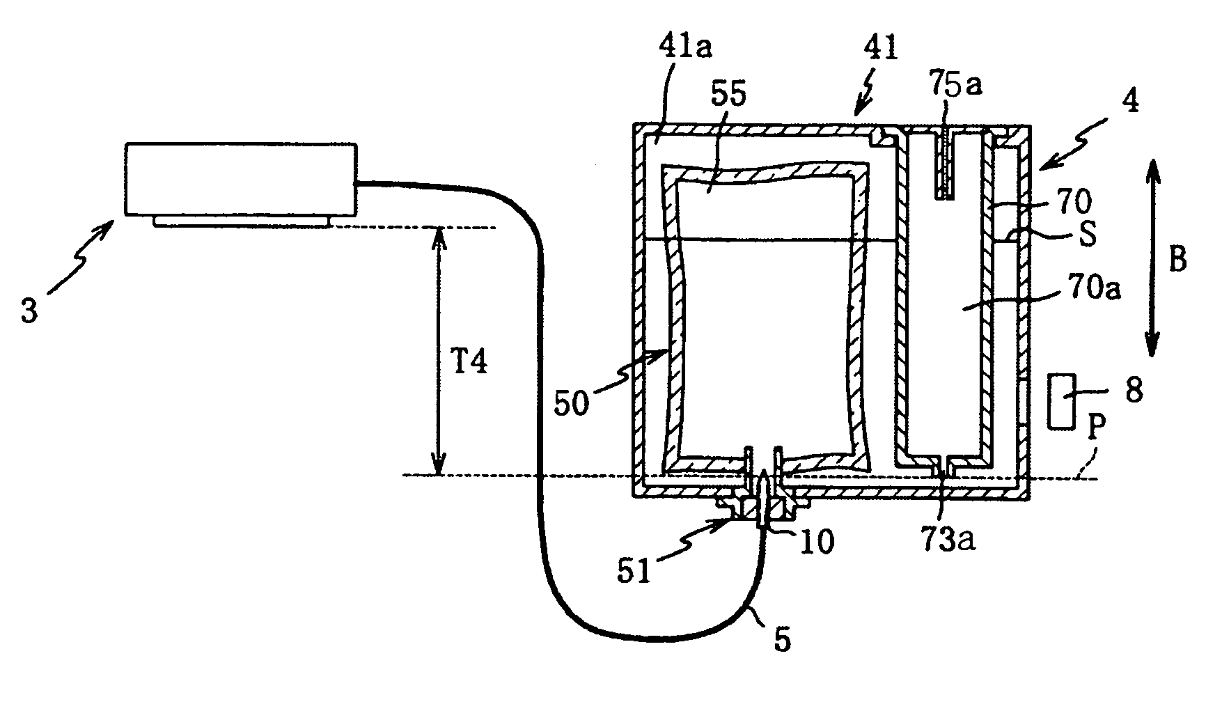
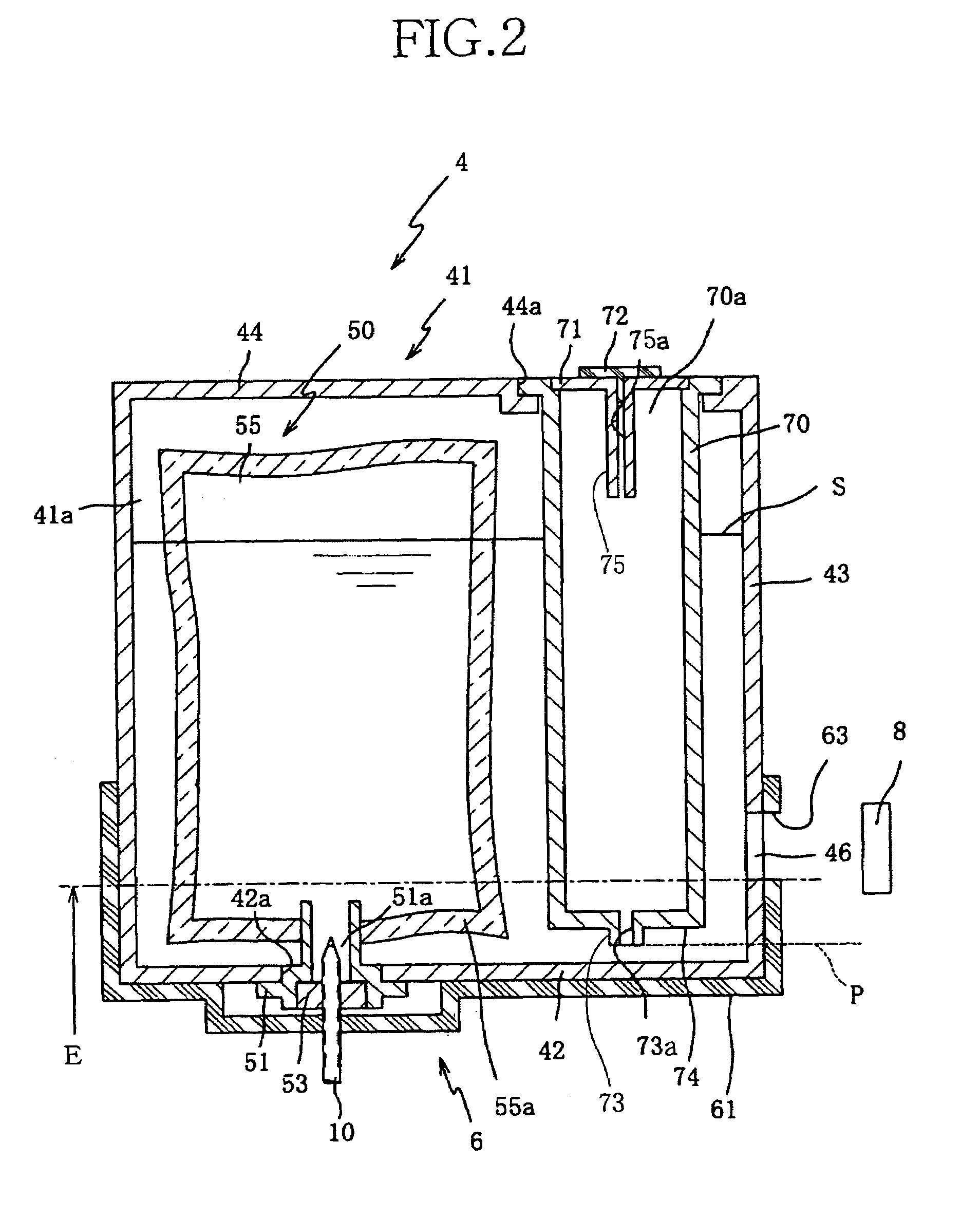
[0010]According to a first aspect of the present invention, there is provided an ink cartridge, comprising an ink storing portion which stores an ink to be supplied to a recording head, and which includes a flexible sheet and an outlet portion through which the ink is supplied to the recording head; a liquid chamber which accommodates a liquid which contacts, under a level thereof, the flexible sheet of the ink storing portion; a gas supplying portion which supplies, as the ink is supplied from the ink storing portion to the recording head and accordingly a volume of the ink storing portion is decreased, a window to detect an interface between the liquid accommodated by the liquid chamber and the gas accumulated above the liquid.
[0012]The reason why the appropriate amount of gas is supplied from the gas supplying portion into the liquid chamber via the liquid-chamber communication hole, so as to compensate for the decrease of pressure of the liquid, caused by the decrease of volume of the ink storing portion, is that the pressure of the gas in the gas supplying portion acts on the liquid at the liquid-chamber communication hole. Therefore, the pressure of the ink held by the recording head can be kept at a certain value, and accordingly the recording head can perform the recording operations with high quality.
[0015]Since the holding portion of the ink jet recording head holds the ink cartridge such that the liquid-chamber communication hole is located at the height position lower than the height position of the interface between the liquid in the liquid chamber and the gas accumulated above the liquid, the pressure of the ink ejected by the recording head is stabilized, and accordingly the recording head can perform the recording operations with high quality.
[0018]Since the reference-position detector detects whether the height position of the interface has reached the reference position corresponding to the pre-determined maximum consumption amount of the ink, a remaining amount of the ink stored by the ink storing portion can be detected with reliability. In addition, since the change of volume of the ink storing portion can be detected by detecting the change of level of the liquid contacting the flexible sheet of the ink storing portion, the change of volume of the ink can be detected with accuracy, without being adversely affected by a possible non-uniform deformation of the flexible sheet of the ink storing portion.

Problems solved by technology

When the height position of the ink level of the ink bag changes, a difference between the height position of the ink level and a height position of the recording head or, in other words, a back pressure acting on the ink present in the recording head changes, which leads to lowering a recording quality of the recording head.
However, in a full-color recording apparatus, a plurality of ink cartridges are arranged in an array in a widthwise direction thereof, which leads to increasing an overall size of the recording apparatus.
On the other hand, in the case where it is required to reduce the overall size of the recording apparatus, a size of each ink bag (i.e., an amount of ink stored in each ink bag) and / or a position where each ink cartridge is attached are / is limited.
In addition, in the case where the ink bag is formed of flexible sheets, those flexible sheets as a whole are not uniformly deformed as the amount of ink decreases.
Therefore, if the deformation of the flexible sheets may directly be detected, or if an electrode may be inserted into the ink bag, it is difficult to detect, with accuracy, a remaining amount of the ink under the condition that the remaining amount is small.

Method used


Image

  • Ink cartridge and ink jet recording apparatus
  • Ink cartridge and ink jet recording apparatus
  • Ink cartridge and ink jet recording apparatus

Examples


Embodiment Construction

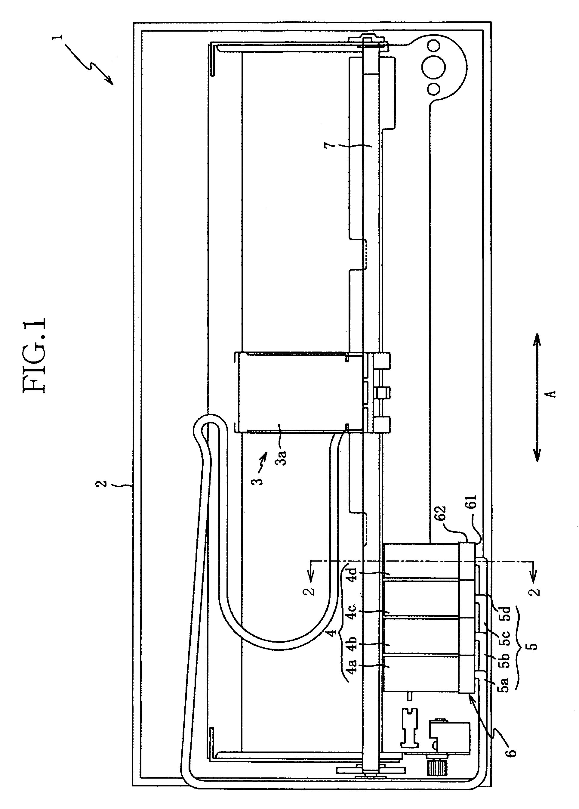
[0023]Hereinafter, there will be described preferred embodiments of the present invention by reference to the drawings. FIG. 1 shows an ink jet recording apparatus 1 which embodies the present invention and which includes four ink cartridges 4 (4a, 4b, 4c, 4d) each of which also embodies the present invention. As shown in FIG. 1, the ink jet recording apparatus 1 includes a housing 2, a recording head unit 3, and the ink cartridges 4. The housing 2 is formed of a fire resistant plastic material and has a generally box-like configuration. The recording head unit 3 is detachably provided in an upper portion of the housing 2. The ink cartridges 4 supply different sorts (i.e., colors) of inks to the recording head unit 3.

[0024]The recording head unit 3 includes a plurality of ink jet recording heads which are mounted on a carriage 3a and each of which ejects an ink toward a recording medium, such as a sheet of paper, so as to record an image on the recording medium. The carriage 3a is s...


PUM


Abstract

An ink cartridge having an ink storing portion which stores an ink to be supplied to a recording head, and which includes a flexible sheet and an outlet portion through which the ink is supplied to the recording head. A liquid chamber accommodates a liquid which contacts under a level thereof, the flexible sheet of the ink storing portion. A gas supplying portion supplies, as the ink is supplied from the ink storing portion to the recording head and accordingly a volume of the ink storing portion is decreased, a gas to the liquid chamber, so that the gas is accumulated above the liquid accommodated by the liquid chamber. A window is provided to detect an interface between the liquid accommodated by the liquid chamber and the gas accumulated above the liquid.

Description

BACKGROUND OF THE INVENTION[0001]1. Field of the Invention[0002]The present invention relates to an ink cartridge and an ink jet recording apparatus and particularly to an ink cartridge and an ink jet recording apparatus each of which assures that ink is ejected with stability as an amount of ink remaining in an ink storing portion decreases.[0003]2. Discussion of Related Art[0004]There is known an ink jet recording apparatus in which ink is supplied from an ink cartridge to a recording head and each of a plurality of nozzles of the recording head ejects a droplet of the ink to record an image on a recording medium such as a sheet of paper.[0005]For example, Japanese Patent Publication No. 61-233551 or its corresponding U.S. Pat. No. 4,719,475 discloses an ink cartridge including an ink bag which stores ink, and an ink jet recording apparatus including the ink cartridge. The ink bag is obtained by bonding flexible sheets to each other, and accordingly has a flat configuration. The f...

Claims


Application Information

Patent Timeline
Patent Type & Authority Patents(United States)
IPC IPC(8): B41J2/175
CPCB41J2/17523B41J2/17509
Inventor KATAYAMA, NAOKI
Owner BROTHER KOGYO KK
Learn More