
Electronic metronome

a metronome and electronic technology, applied in the field of electronic metronomes, can solve the problems of embarrassing a professional performer to listen to the click sound using the conventional metronome on the stage, and achieve the effect of eliminating the inconvenience of operating the switching devi

Inactive Publication Date: 2006-07-25
SEIKO INSTR INC
View PDF3 Cites 3 Cited by
  • Summary
  • Abstract
  • Description
  • Claims
  • Application Information

AI Technical Summary

Benefits of technology

The present invention provides an electronic metronome with a sound emitting portion, display portion, and vibration outputting portion for outputting a sound and vibration representing the tempo. The vibration outputting portion includes a vibration source and a switch for starting and stopping the vibration. The vibration source can be an eccentric motor with a cylindrical shape. The electronic metronome can also include a vibration level adjusting portion for controlling the strength of the vibration. The vibration device can be placed in the vicinity of a performer and can be used to train the user to master a good sense of tempo. The vibration device can output only the vibration independently without the click sound being outputted, and the user can select whether or not the vibration is to be outputted through a switching device. The vibration device allows the user to train himself / herself to master a good sense of tempo when necessary and can be operated without the need for a switching device. The vibration device is caused to vibrate constantly, so that the inconvenience of operating the switching device can be eliminated.

Problems solved by technology

However, it would definitely embarrass a professional performer to listen to the click sound using the conventional metronome on a stage.

Method used


Image

  • Electronic metronome
  • Electronic metronome
  • Electronic metronome

Examples


Embodiment Construction

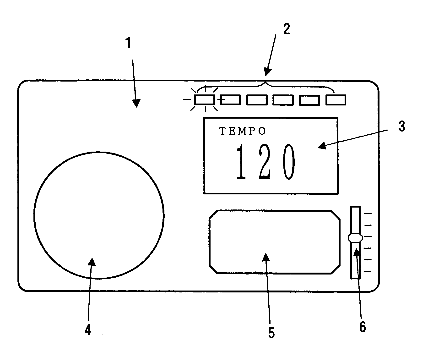
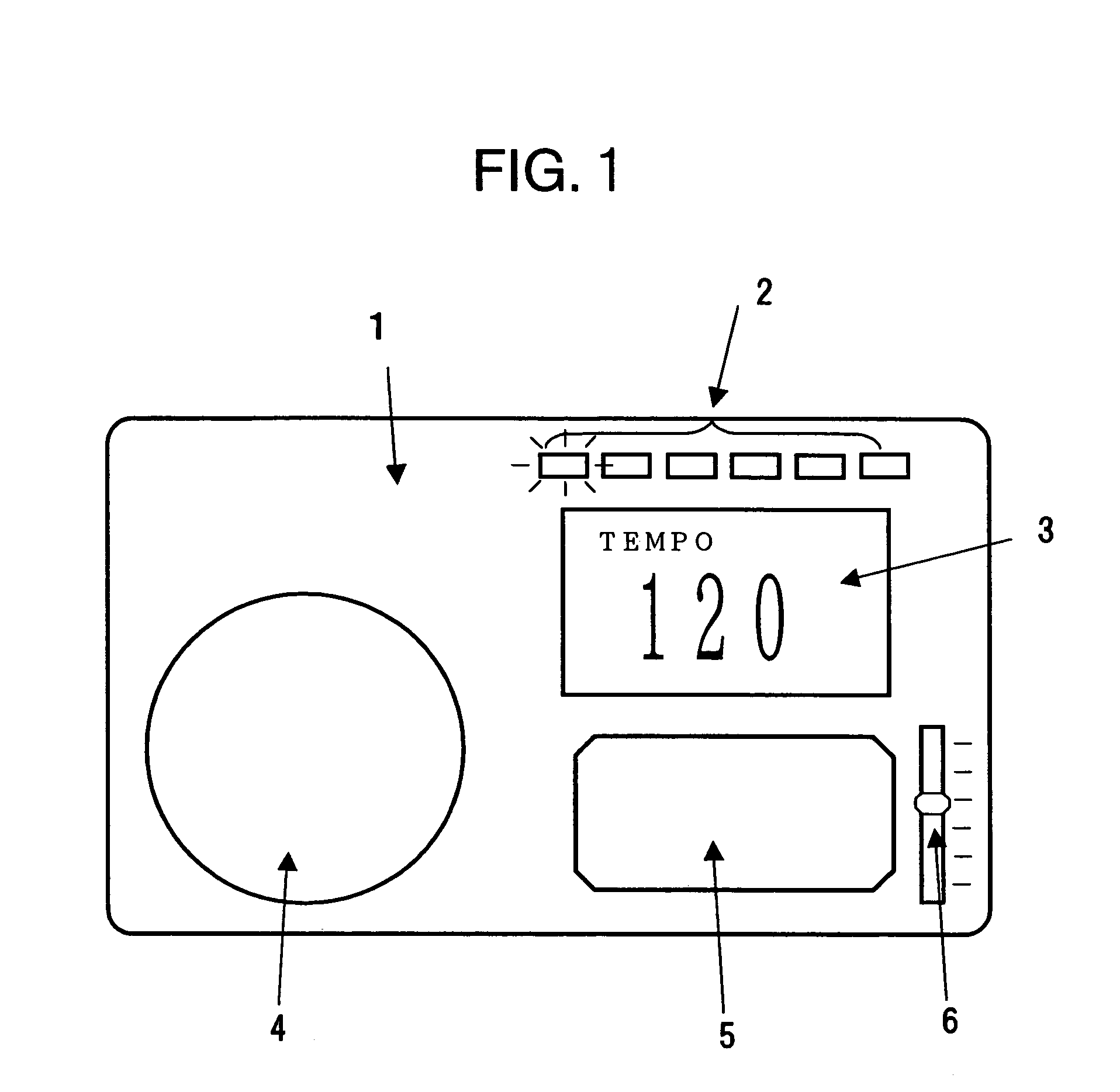
[0028]In FIG. 1, a casing 1 of an electronic metronome includes a tempo displaying LED portion 2 for indicating a tempo, a display portion 3 for displaying a numerical value of the tempo, a sound emitting device 4 for emitting a sound representing the tempo, and a vibration device 5 for generating a vibration representing the tempo. The tempo set by a user is displayed on the display portion 3, and the tempo is indicated by a state where LEDs lined in the tempo displaying LED portion 2 are lit so as to have the lit LED reciprocate. Similarly, the sound emitting device 4 outputs a click sound based on the set tempo, and the vibration device 5 vibrates in synchronization with the click sound. A vibration strength adjusting volume 6 is used to adjust the strength of the vibration generated by the vibration device 5.

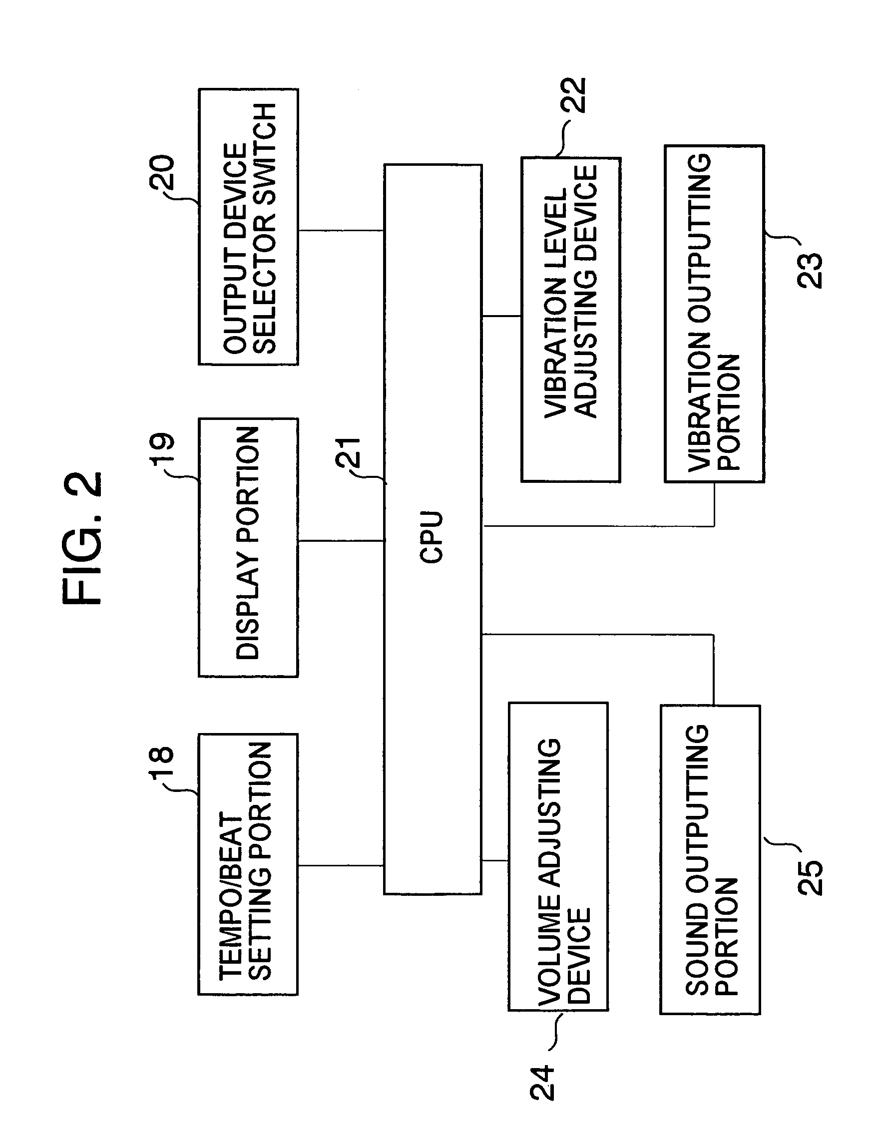
[0029]FIG. 2 is a block diagram showing a configuration example of the electronic metronome according to the present invention. Tempo and beat information inputted and set b...


PUM


Abstract

An electronic metronome has a casing including a display portion for displaying a numerical value of a tempo, a sound emitting device for emitting a sound representing the tempo, a vibration device for generating a vibration representing the tempo, and a vibration level adjusting device for adjusting the stregth of the vibratrion. The vibration is used for notifying a tempo to a user, whereby the user can master a good sense of tempo efficiently without being affected by the surrounding environment. The electronic metronome prevents the phenomenon that if a user performs a musical piece specified with a slow tempo immediately after performing a musical piece specified with a fast tempo, the user may perform the piece at a faster tempo than the originally intended slow tempo.

Description

BACKGROUND OF THE INVENTION[0001]1. Field of the Invention[0002]The present invention relates to an electronic metronome.[0003]2. Description of the Related Art[0004]Conventionally known is an electronic metronome in which means for causing a user to sense a tempo set at will by the user indicates the tempo by flashing an LED according to the set tempo, or notifies the tempo by a click sound outputted from a sound emitting device.[0005]The conventional electronic metronome merely functions to light the LED or emit a click sound according to the set tempo. In the case where the user performs a plurality of musical pieces in a situation such as a concert, there may occur a phenomenon that if the user performs a musical piece specified with a slow tempo immediately after performing a musical piece specified with a fast tempo, the user may perform the piece at a faster tempo than an originally intended tempo. In order to prevent the phenomenon, a performer uses a metronome or the like t...

Claims


Application Information

Patent Timeline
Patent Type & Authority Patents(United States)
IPC IPC(8): G09B15/00G04F5/02
CPCG09B15/00G04F5/025
Inventor NAGAKURA, FUMIYOSHI
Owner SEIKO INSTR INC
Learn More