Power factor corrected UPS with improved connection of battery to neutral

a power factor and battery technology, applied in emergency power supply arrangements, instruments, process and machine control, etc., can solve the problems of further complicated pfc circuits, inability to maintain the integrity of neutrals, and inconvenient ups design. achieve the effect of simple and efficient circuits

Inactive Publication Date: 2006-07-25
EATON POWER QUALITY CORP
View PDF22 Cites 27 Cited by
  • Summary
  • Abstract
  • Description
  • Claims
  • Application Information

AI Technical Summary

Benefits of technology

[0008]It is an object of this invention to provide a power factor corrected UPS which maintains neutral integrity from the input of the UPS to an output terminal to which the load is connected, the UPS device having a simple and efficient circuit for connecting the battery to the converter of the PFC circuit, whereby whenever the battery provides output power due to deterioration of the utility line voltage, battery voltage is converted through the PFC converter and delivered to the high voltage rails. The UPS achieving this object provides an uninterrupted neutral from its input connection to the AC power line through to an output terminal for connection to the load, balances the battery around neutral, and achieves supply of the battery power independently to the high voltage rails without the need of an independent battery to HV rail converter, or the need for any isolation means.
[0009]In a first embodiment, a four diode-two capacitor circuit is used to connect the battery to the PFC converter. During normal operation when the UPS is drawing power from the utility line, the battery is balanced around neutral and is maintained no more than one forward diode dram away from neutral. By using a battery with a voltage less than one-half of the peak of the incoming AC voltage, the PFC circuit is substantially unaffected so that power factors greater than 0.9 can be achieved. During loss of AC input, when the UPS runs on battery, switching elements of the PFC converter are independently turned on and off, enabling conversion of the battery voltage through the PFC converter circuitry to the HV lines. In a second, preferred embodiment, one terminal of the battery is connected directly to neutral, and the other terminal is connected through a normally open switch and a diode to the converting circuit. The switch is closed when low AC power line voltage is sensed. Both embodiments thus enable elimination of a separate converter for the battery while preserving the advantages of prior art power factor corrected UPS devices maintaining integrity of the neutral connection from input to load.

Problems solved by technology

Because of the inherent nature and mode of operation of typical UPS systems, conventional UPS designs did not maintain the integrity of the neutral through the processing circuitry, requiring some type of isolation means such as isolation transformer to re-establish the neutral at the load.
The problem with maintaining integrity of the neutral is further complicated in a UPS having a power factor correction circuit.
And, the incorporation of such a PFC circuit imposes additional difficulties upon the goal of maintaining integrity of a neutral connection from the power line to the load.
The problem is thus how to provide that the converted output from the PFC circuit, as well as the battery output, can be independently loaded and still balanced around neutral to the plus and minus HV rails without using a separate converter of some sort for each.

Method used


Image

  • Power factor corrected UPS with improved connection of battery to neutral
  • Power factor corrected UPS with improved connection of battery to neutral
  • Power factor corrected UPS with improved connection of battery to neutral

Examples


Embodiment Construction

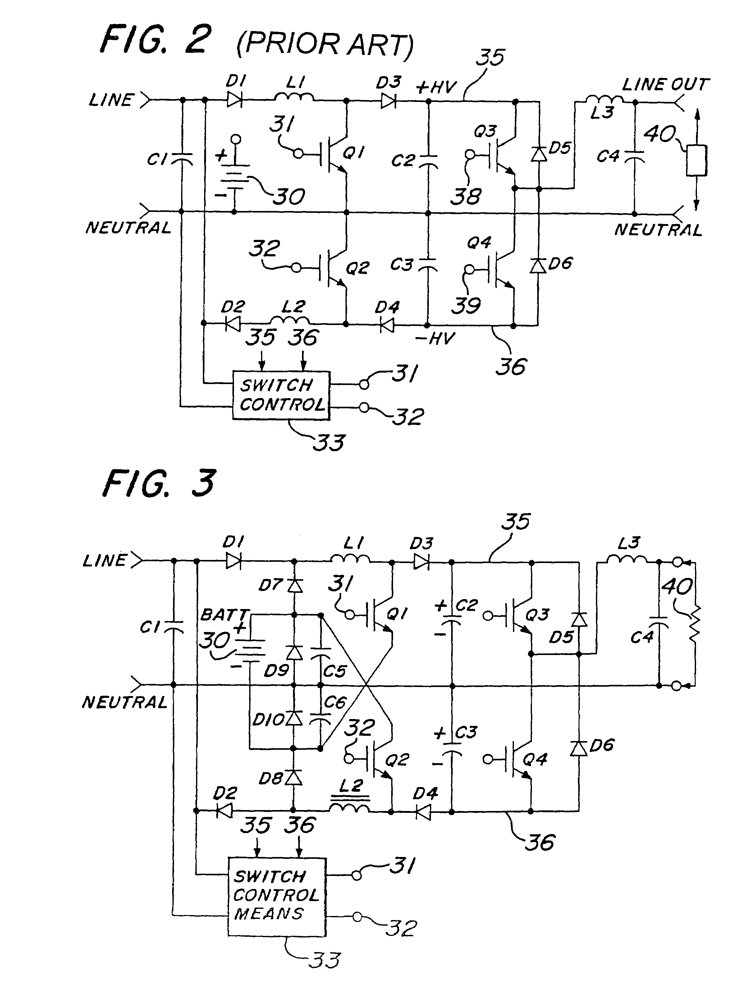
[0018]Referring now to FIG. 2, there is shown a circuit diagram of a typical power factor corrected UPS with an uninterrupted neutral from input to output. The AC input is connected to the UPS at two input terminals, one of which is marked “line” and the other of which is marked “neutral.” The neutral line is connected by an uninterrupted conductor to one of two output terminals, across which AC output power is delivered. The AC input signal is connected across a first capacitor C1. The line terminal is connected to rectifier diodes D1 and D2. D1 is in series with inductor L1, the other side of L1 being connected through switching transistor Q1 to neutral. D2 is connected in series with inductor L2, the other side of L2 being connected through switching transistor Q2 to neutral. The input terminals 31, 32 are driven by switch control means 33 such as illustrated in FIG. 1 of U.S. Pat. No. 4,980,812, incorporated herein by reference. Transistors Q1 and Q2 of FIG. 2 correspond to tran...


PUM


Abstract

An uninterrupted power supply (UPS) device with uninterrupted neutral from input to output utilizes the same converter for converting rectified AC power and battery power to positive and negative high voltage (HV) rails. A simple circuit is utilized for connecting the battery to the conversion components of the PFC circuit without adverse affect on the performance of the PFC circuit, and while holding the battery substantially connected to neutral. In a first embodiment, the circuit comprises a simple combination of four diodes and a pair of high pass capacitors arranged so that in both power line and battery supply modes the battery is balanced around neutral. In a second, preferred embodiment, one terminal of the battery is connected directly to neutral.

Description

RELATED APPLICATIONS[0001]This application is a continuation of prior application Ser. No. 10 / 378,187 filed Mar. 3, 2003, now U.S. Pat. No. 6,944,035, which is a continuation of prior application Ser. No. 10 / 151,449 filed May 20, 2002, now U.S. Pat. No. 6,661,678, which is a continuation of prior application Ser. No. 09 / 812,993 filed Mar. 20, 2001, now U.S. Pat. No. 6,400,586, which is a continuation of prior application Ser. No. 09 / 563,462 filed May 2, 2000, now U.S. Pat. No. 6,262,899, which is a continuation of application Ser. No. 08 / 038,469 filed Mar. 29, 1993, now U.S. Pat. No. 6,069,412, the disclosures of which are hereby incorporated herein by reference.BACKGROUND OF THE INVENTION[0002]1. Field of the Invention[0003]This invention relates to uninterrupted power supply (UPS) apparatus and, more particularly, to a power factor corrected UPS maintaining integrity of the connection from power line neutral to an output load terminal.[0004]2. Description of the Prior Art[0005]UPS...

Claims


Application Information

Patent Timeline
Patent Type & Authority Patents(United States)
IPC IPC(8): H02M3/335H02M1/14H02J9/06H02M1/00H02M1/42H02M5/458
CPCH02J9/062H02M1/4208H02M5/458Y02B70/126H02M2001/007H02M1/007Y02B70/10
Inventor RADDI, WILLIAM J.PAULAKONIS, JOSEPH C.JOHNSON, JR., ROBERT W.
Owner EATON POWER QUALITY CORP
Why Eureka
Try Eureka