Manufacturing method for cylindrical part

a manufacturing method and cylindrical technology, applied in the field of cylindrical parts, can solve the problems of increasing the manufacturing cost, not being able to form an inner side step portion at the boundary between the thin-walled portion and the heavy-walled portion, so as to achieve the effect of easy removal from the die and preventing the adhesion of the base metal to the die or the punch

Active Publication Date: 2006-08-01
NIHON PAKKIN +1
View PDF13 Cites 3 Cited by
  • Summary
  • Abstract
  • Description
  • Claims
  • Application Information

AI Technical Summary

Benefits of technology

[0020]It is a further object of the present invention to provide a method of manufacturing the cylindrical part with the thin-walled portion at a lower cost, and according to the manufacturing method of the present invention, a base metal formed with thin-walled portion adjacent to its closed end can be easily detached from working jigs, such as a die, a punch and so on.
[0021]It is a further object of the present invention to provide a manufacturing method, according to which a thin-walled portion as well as a heavy-walled portion for a cylindrical part can be manufactured with a higher accuracy, even if there exist variations in thickness of a base metal.
[0022]According to a feature of the present invention, a cup-shaped base metal is at first formed, which has a cylindrical wall, a closed end and an open end at both sides of the cylindrical wall. A thin-walled portion is then formed by an ironing process on a portion of the cylindrical wall adjacent to the closed end, so that an outer-side step portion is formed between the thin-walled portion and the remaining (heavy-walled) portion of the cylindrical wall due to a difference of thickness of the walls of two portions. The closed end of the base metal is punched out, so that the thin-walled portion remains at the base metal. Then, the thin-walled portion is outwardly enlarged in its radial direction. As above, the cylindrical part having the thin-walled portion as well as an inner-side step portion can be manufactured by the ironing process, so that the manufacturing cost becomes lower than a method of a cutting process. Furthermore, a plunging force to the base metal by the working jigs (a die, a punch, an so on) can be made smaller than that in a backward extrusion process, so that an adhesion of the base metal to the working jigs can be prevented and thereby the base metal can be easily detached from the working jigs. Furthermore, a working force for the working jigs can be made smaller compared with the backward extrusion process, so that the lifetime of the working jigs can be elongated and the change of shape for the base metal can be prevented.
[0023]During the ironing process of the cylindrical wall adjacent to the closed end to form a thin-walled portion and a heavy-walled portion, a portion of the cylindrical wall is longitudinally extended so that a material of those portion flows from the thin-walled portion to the heavy-walled portion. When there are variations in thickness of the base metal for the cylindrical wall, a material volume flowing from the thin-walled portion to the heavy-walled portion varies depending on the variations of the thickness of the base metal, even when a length of longitudinal extension is controlled at a constant value. As a result, a dimensional accuracy at the heavy-walled portion may be decreased. Accordingly, in another feature of the present invention, a longitudinal length of the thin-walled portion, which will be formed by the ironing process at the cylindrical portion adjacent to the closed end, is adjusted depending on the thickness of the base metal.
[0024]According to a further feature of the present invention, when a thin-walled portion is formed by the ironing process at the cylindrical wall adjacent to the closed end, a longitudinal length of the thin-walled portion is made longer than a longitudinal length of the final product of the cylindrical part. And a positioning step portion is formed by the ironing process on the thin-walled portion at such a position, which corresponds to the longitudinal length required for the final product of the cylindrical part, and then the closed end is punched out. Accordingly, a dimensional accuracy for the longitudinal length of the thin-walled portion can be enhanced.
[0027]However, as mentioned above, the thin-walled portions are formed by the ironing process according to the present invention, the adhesion of the base metal to the die or the punch can be prevented and can be easily detached from the die and the punch, even when the thickness of the thin-walled portions is less than 3 mm.

Problems solved by technology

It is, however, disadvantageous in that a manufacturing cost will be increased because a working time becomes longer if the thin-walled portion 302 is formed by the cutting process.
In FIGS. 14A and 14B, the material backwardly flows in an inner surface of the base metal, the same problem may occur in the case that a thin-walled portion is formed wherein a material backwardly flows in an outer surface of a base metal.
In the above method for manufacturing the thin-walled portion adjacent to the closed end of the cylindrical base metal by the ironing process, however, it is not possible to form an inner side step portion at a boundary between the thin-walled portion and a heavy-walled portion.

Method used


Image

  • Manufacturing method for cylindrical part
  • Manufacturing method for cylindrical part
  • Manufacturing method for cylindrical part

Examples


Embodiment Construction

[0046]An embodiment of the present invention will be explained with reference to the drawings, wherein an inner diameter and an outer diameter respectively designate a radius.

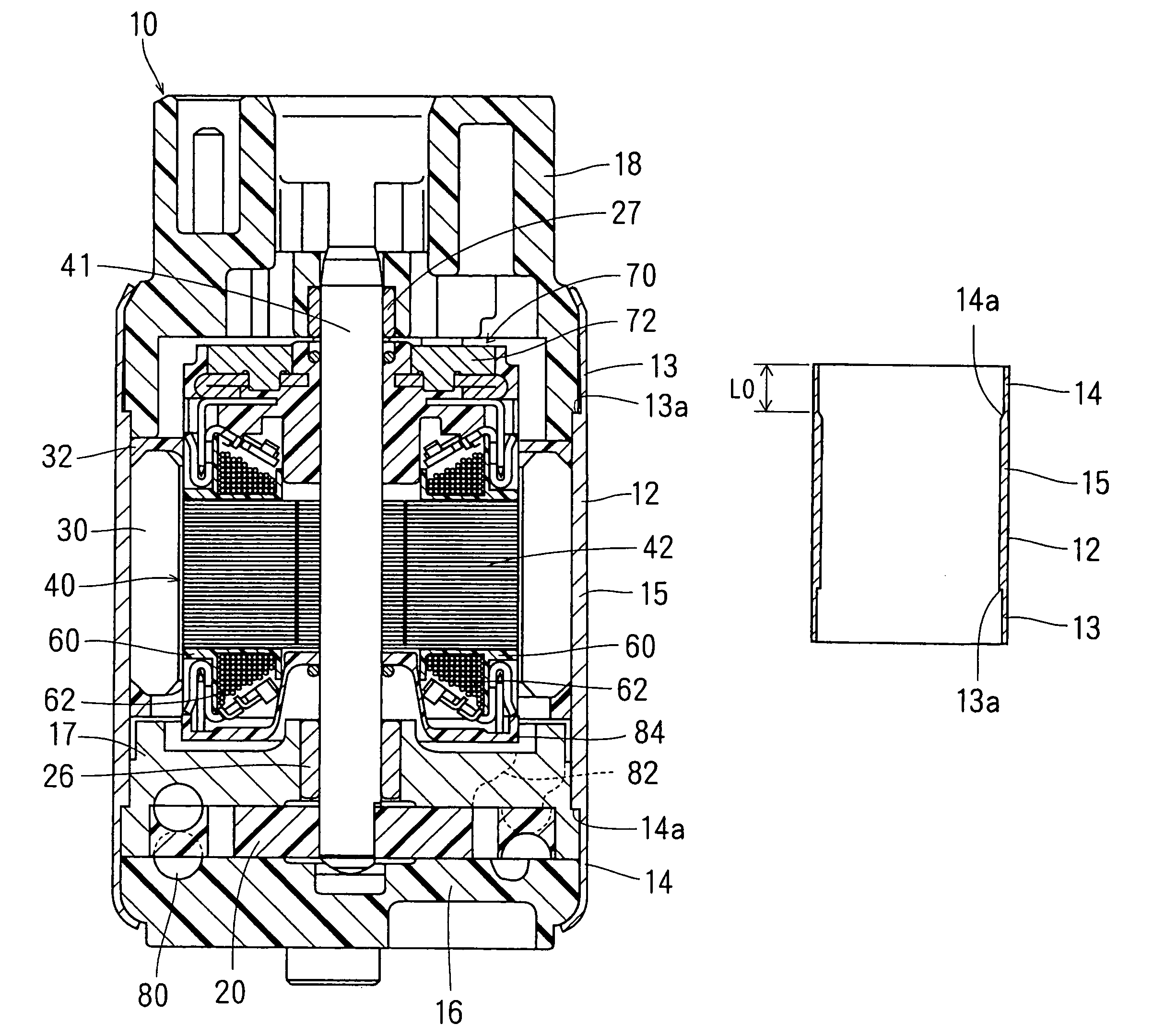
[0047]A fuel pump according to an embodiment of the present invention is shown in FIG. 1. The fuel pump 10 is, for example, an in-tank type pump installed in a fuel tank of a motor vehicle. A housing 12 of a cylindrical shape is made of an iron or steel. The housing 12 is composed of thin-walled portions 13, 14 at both longitudinal ends, and a heavy-walled portion 15 between the thin-walled portions 13, 14. An inlet side cover 16 and a discharge side cover 18 are fixed to the housing 12 at the thin-walled portions 13, 14 by a caulking process (inwardly bending a peripheral end of the respective thin-walled portions). Inner-side step portions 13a and 14a are formed at an inner peripheral surface of the housing 12 at boundaries between the heavy-walled portion 15 and the thin-walled portions 13, 14. The thickness...


PUM

PropertyMeasurementUnit
thicknessaaaaaaaaaa
thicknessaaaaaaaaaa
thicknessaaaaaaaaaa

Abstract

It is an object of the present invention to provide a method of manufacturing a cylindrical part with a thin-walled portion at a lower cost, and according to the manufacturing method of the present invention, a base metal formed with thin-walled portion adjacent to its closed end can be easily detached from working jigs. According to the method, a thin-walled portion is at first formed by the ironing process on a cylindrical wall adjacent to the closed end, so that an outer-side step portion is formed on an outer peripheral surface of the cylindrical wall. Then the closed end is punched out and the thin-walled portion is enlarged in a radial and outward direction to form an inner-side step portion on an inner peripheral surface of the cylindrical part.

Description

CROSS REFERENCE TO RELATED APPLICATION[0001]This application is based on Japanese Patent Application No. 2003-394166 filed on Nov. 25, 2003, the disclosure of which is incorporated herein by reference.FIELD OF THE INVENTION[0002]This invention relates to a manufacturing method for a cylindrical part, which has a thin-walled portion at least at one longitudinal end.BACKGROUND OF THE INVENTION[0003]As a method for manufacturing a cylindrical part having a thin-walled portion, such as, for example, a cylindrical part 300 with a thin-walled portion 302 at its one end, as shown in FIG. 13, a cutting process is possible. It is, however, disadvantageous in that a manufacturing cost will be increased because a working time becomes longer if the thin-walled portion 302 is formed by the cutting process.[0004]As another method for manufacturing the cylindrical part with the thin-walled portion 302, an extrusion process can be applied, as disclosed in the following publications:[0005]Japanese P...

Claims


Application Information

Patent Timeline
Patent Type & Authority Patents(United States)
IPC IPC(8): B21K21/12B21D22/28B21D35/00B21D51/18
CPCB21D22/28B21D35/00Y10T29/4994Y10T29/49833
Inventor EZAKA, SHINICHISUGIYAMA, SATOSHIMATSUURA, TOMOHIROWATANABE, TAKAFUMIITO, TATSUYATAKO, NOBUHISA
Owner NIHON PAKKIN
Why Eureka
Try Eureka