
Pressure controlled fluid sampling apparatus and method

a fluid sampling and pressure control technology, applied in the direction of survey, borehole/well accessories, insulation, etc., can solve the problems of large cost and time, inability to preserve the temperature and/or pressure of the formation fluid, and relatively complex operation to remove the formation fluid sampl

Active Publication Date: 2006-08-01
SCHLUMBERGER TECH CORP
View PDF56 Cites 67 Cited by
  • Summary
  • Abstract
  • Description
  • Claims
  • Application Information

AI Technical Summary

Benefits of technology

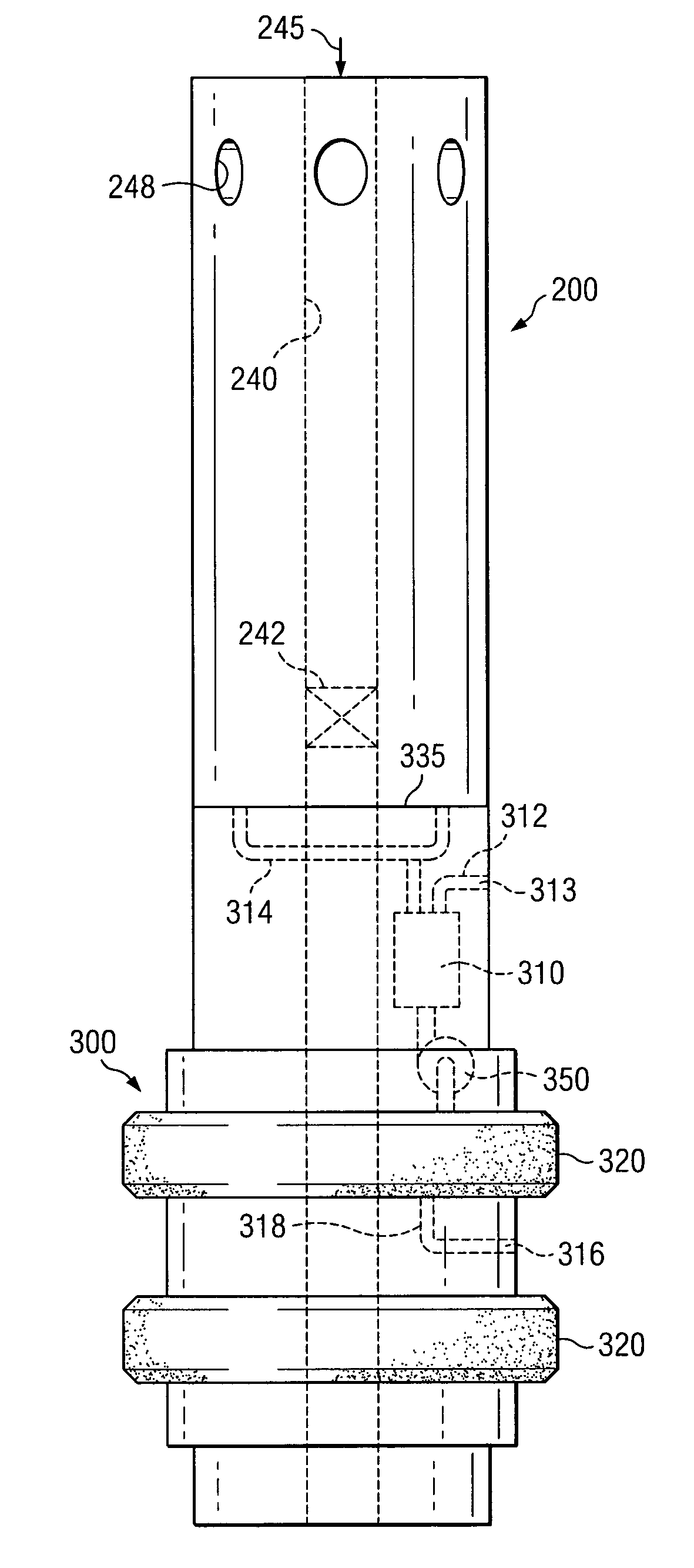
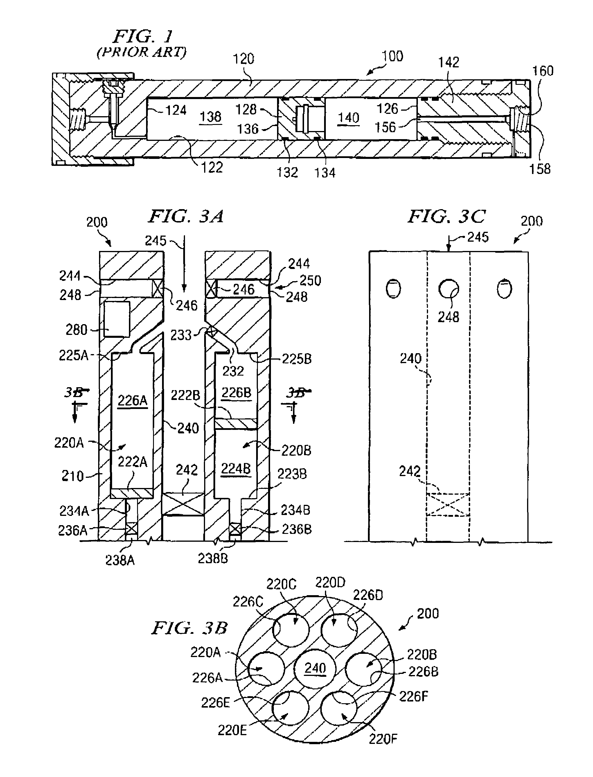
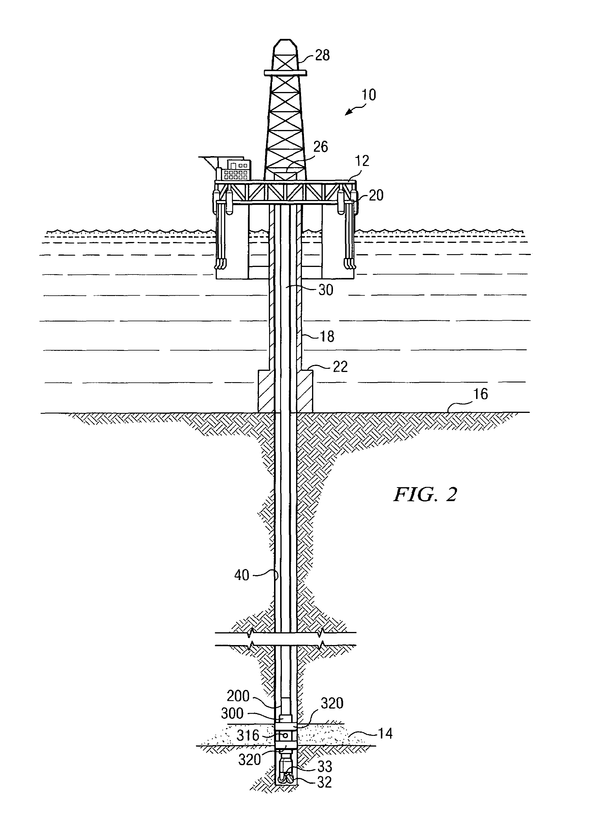
The present invention provides a formation fluid sampling tool that can be used during drilling operations to collect samples of formation fluid. The tool includes a sample tank with an internal fluid separator and a sample inlet port for controlling the temperature of the sample. The tool can be coupled with a drill string to receive samples from a well bore without removing the drill string. The tool can also include a heating module to control the temperature of the sample. Additionally, the invention includes a logging while drilling tool that includes the sampling tool and a packer assembly for sealing the well bore. The method of acquiring a formation fluid sample involves using the sampling tool and pumping formation fluid into the sample chamber. The technical effects of the invention include improved efficiency and accuracy in acquiring formation fluid samples during drilling operations.

Problems solved by technology

While the Berger and Schultz apparatuses apparently permit samples to be collected relatively early in the life of a well, without retrieval of the drill string, they include no capability of preserving the temperature and / or pressure of the formation fluid.
Further, it is a relatively complex operation to remove the formation fluid sample from the Berger apparatus.
One drawback of the Michaels and Massie apparatuses is that they require prior withdrawal of the drill string before they can be lowered into the well bore, which typically involves significant cost and time, and increases the risk of subsurface damage to the formation of interest.

Method used


Image

  • Pressure controlled fluid sampling apparatus and method
  • Pressure controlled fluid sampling apparatus and method
  • Pressure controlled fluid sampling apparatus and method

Examples


Embodiment Construction

[0022]The present invention addresses difficulties in acquiring and preserving samples of pristine formation fluid, including those difficulties described above. This invention includes a sampling tool for obtaining samples of relatively pristine formation fluid without removing the drill string from the well bore. Sampling tools according to this invention may retrieve samples from any depth, including both deep and shallow wells. Embodiments of the sampling tool of this invention are configured for coupling to a drill string and include a through bore, allowing drilling fluid (such as drilling mud) to flow therethrough. Embodiments of the tool include one or more sample tanks, each of which advantageously includes a movable internal fluid separator disposed therein which divides the tank into a sample chamber and a pressure balancing chamber. In one embodiment, the pressure balancing chamber may be in fluid communication with the through bore and thus pressure balanced with the dr...


PUM


Abstract

A formation fluid sampling tool including at least one sample tank mounted in a tool collar. The tool collar includes a through bore and is disposed to be operatively coupled with a drill string such that each sample tank may receive a correspondingly preselected formation fluid sample without removing the drill string from a well bore. At least one of the sample tanks further includes an internal fluid separator movably disposed therein. The separator separates a sample chamber from a pressure balancing chamber in the sample tank. The pressure balancing chamber is disposed to be in fluid communication with drilling fluid exterior thereto. The sampling tool further includes a sample inlet port connected to the sample chamber by an inlet passageway.

Description

FIELD OF THE INVENTION[0001]The present invention relates generally to the drilling of oil and / or gas wells, and more specifically, to a formation fluid sampling tool and method of use for acquiring and preserving substantially pristine formation fluid samples.BACKGROUND INFORMATION[0002]The commercial development of hydrocarbon (e.g., oil and natural gas) fields requires significant capital investment. Thus it is generally desirable to have as much information as possible pertaining to the contents of a hydrocarbon reservoir and / or geological formation in order to determine its commercial viability. There have been significant advances in measurement while drilling and logging while drilling technology in recent years (hereafter referred to as MWD and LWD, respectively). These advances have improved the quality of data received from downhole sensors regarding subsurface formations. It is nonetheless still desirable to obtain one or more formation fluid samples during the drilling a...

Claims


Application Information

Patent Timeline
Patent Type & Authority Patents(United States)
IPC IPC(8): E21B49/08E21B36/04
CPCE21B49/081E21B49/08
Inventor PALUCH, WILLIAM C.MOODY, MICHAEL J.
Owner SCHLUMBERGER TECH CORP
Learn More