Pump Control for Formation Testing

a technology of pump control and formation testing, applied in the direction of survey, instruments, borehole/well accessories, etc., can solve the problems of equipment failure or less than optimal performance, take up to several hours, and complicate the matter further

Active Publication Date: 2008-07-03
SCHLUMBERGER TECH CORP
View PDF17 Cites 92 Cited by
  • Summary
  • Abstract
  • Description
  • Claims
  • Application Information

AI Technical Summary

Problems solved by technology

A combination of removing the drill string and lowering the wireline tools downhole are time-consuming measures and can take up to several hours, depending upon the depth of the borehole.
Because of the great expense and rig time required to “trip” the drill pipe and lower the wireline tools down the borehole, wireline tools are generally used only when the information is absolutely needed or when the drill string is tripped for another reason, such as changing the drill bit.
However, as one can imagine, multiple moving parts involved in any formation testing tool, either of wireline or MWD, can result in equipment failure or less than optimal performance.
Further, at significant depths, substantial hydrostatic pressure and high temperatures are experienced thereby further complicating matters.

Method used


Image

  • Pump Control for Formation Testing
  • Pump Control for Formation Testing
  • Pump Control for Formation Testing

Examples


Embodiment Construction

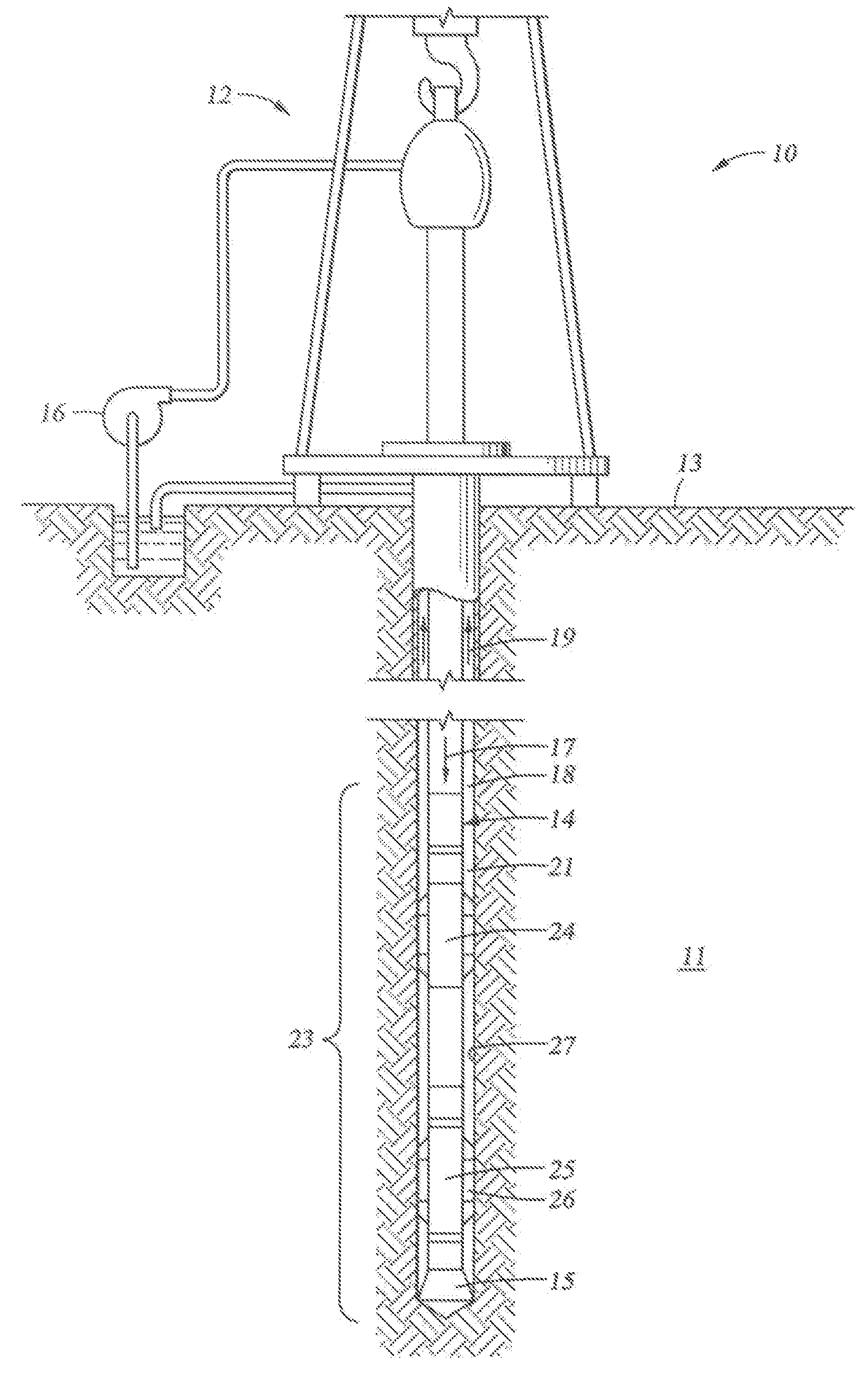
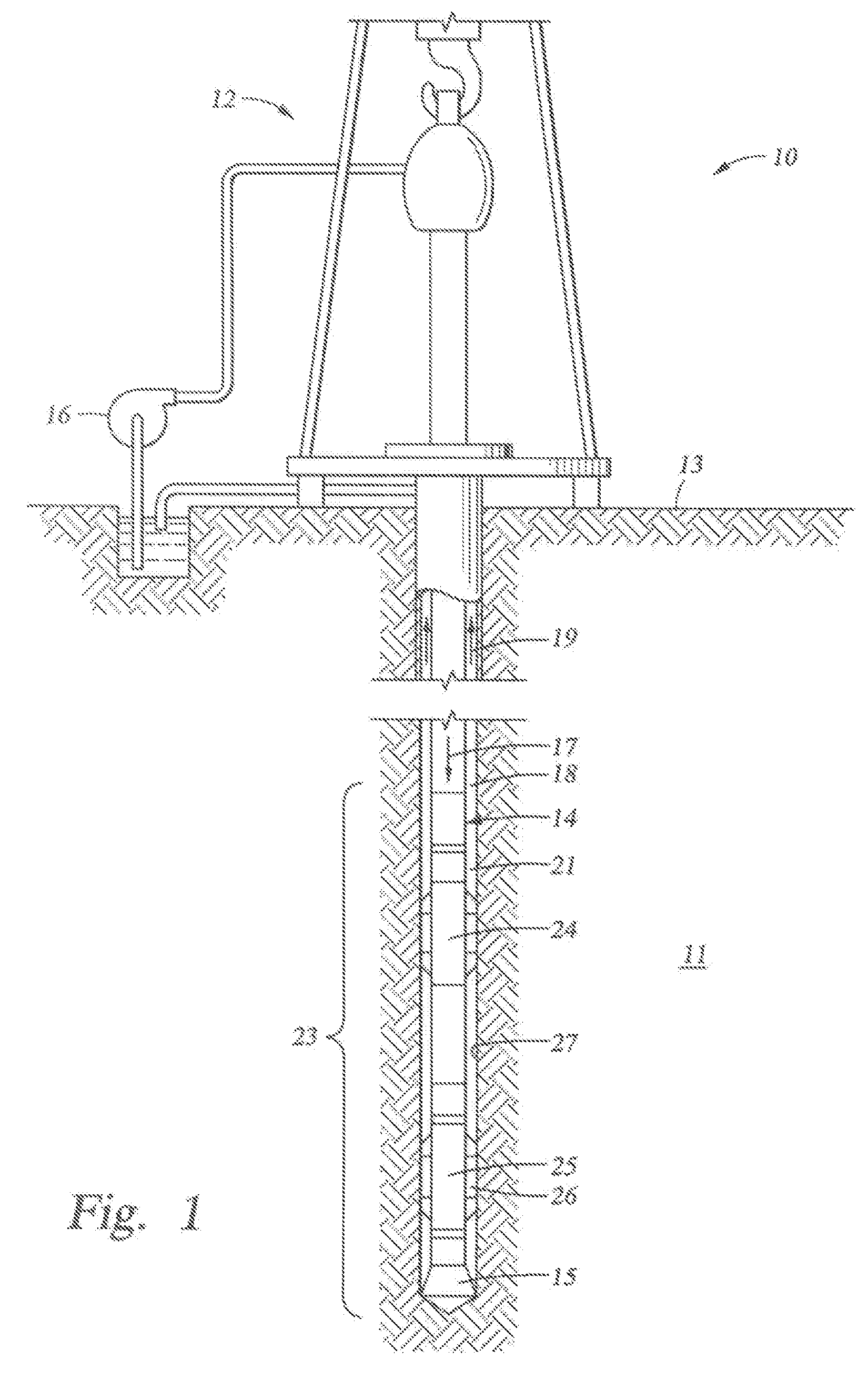
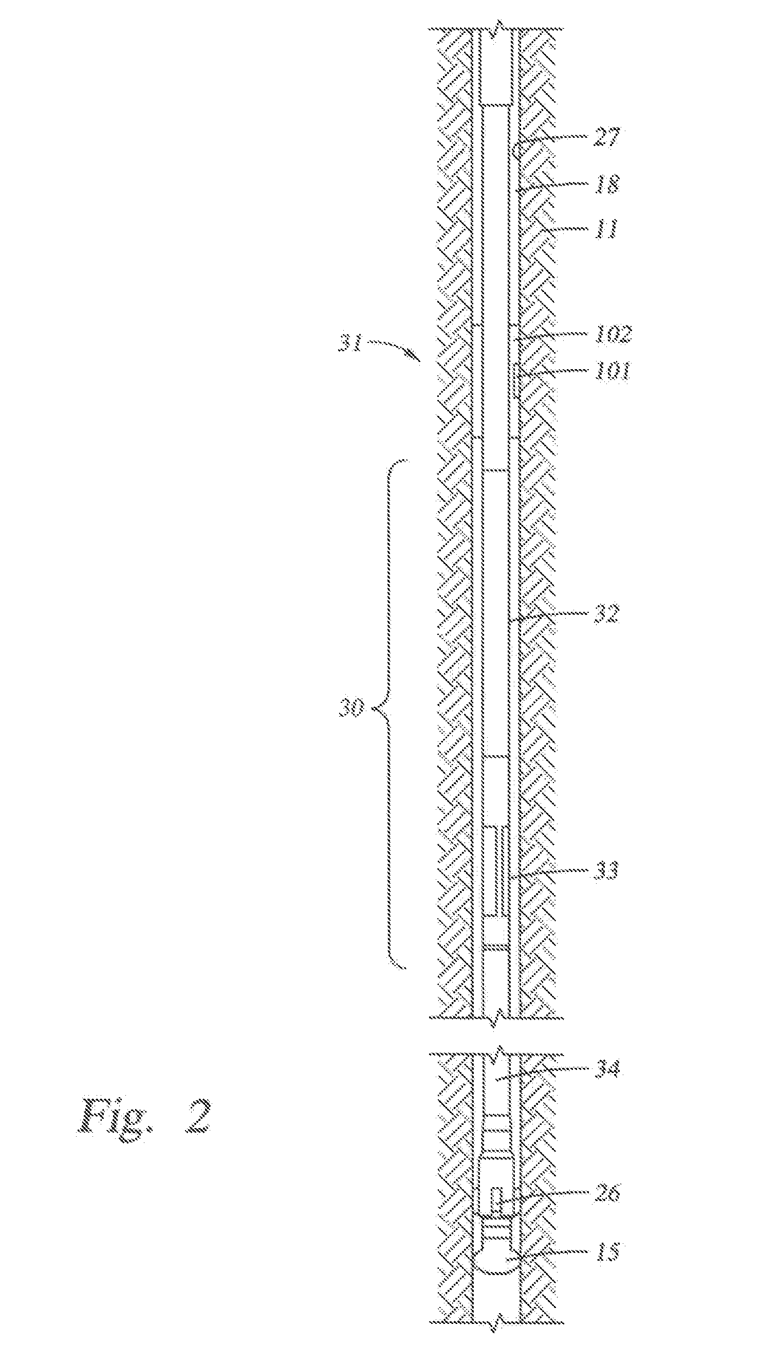
[0029]This disclosure relates to fluid pumps and sampling systems described below and illustrated in FIGS. 2-8 that may be used in a downhole drilling environment, such as the one illustrated in FIG. 1. In some refinements, this disclosure relates to methods for using and controlling the disclosed fluid pumps. In one or more refinements, a formation evaluation while drilling tool includes an improved fluid pump and an improved method of controlling the operation of the pump. In some other refinements, improved methods of formation evaluation while drilling are disclosed

[0030]Those skilled in the art given the benefit of this disclosure will appreciate that the disclosed apparatuses and methods have application during operation other than drilling and that drilling is not necessary to practice this invention. While this disclosure relates mainly to sampling, the disclosed apparatus and method can be applied to other operations including injection techniques.

[0031]The phrase “formatio...


PUM


Abstract

A downhole formation fluid pumping and a sampling apparatus are disclosed that may form part of a formation evaluation while drilling tool or part of a tool pipe string. The operation of the pump is optimized based upon parameters generated from formation pressure test data as well as tool system data thereby ensuring optimum performance of the pump at higher speeds and with greater dependability. New pump designs for fluid sampling apparatuses for use in MWD systems are also disclosed.

Description

BACKGROUND[0001]1. Technical Field[0002]This disclosure is directed toward geological formation testing. More specifically, this disclosure is directed toward controlling the pump or fluid displacement unit (FDU) of a formation testing tool.[0003]2. Description of the Related Art[0004]Wells are generally drilled into the ground or ocean bed to recover natural deposits of oil and gas, as well as other desirable materials, that are trapped in geological formations in the Earth's crust. A well is typically drilled using a drill bit attached to the lower end of a “drill string.” Drilling fluid, or “mud,” is typically pumped down through the drill string to the drill bit. The drilling fluid lubricates and cools the drill bit, and it carries drill cuttings back to the surface in the annulus between the drill string and the borehole wall.[0005]For successful oil and gas exploration, it is necessary to have information about the subsurface formations that are penetrated by a borehole. For e...

Claims


Application Information

Patent Timeline
Patent Type & Authority Applications(United States)
IPC IPC(8): E21B49/08G05D7/00
CPCE21B49/10E21B4/02E21B49/08
Inventor CIGLENEC, REINHARTVILLAREAL, STEVEN G.HOEFEL, ALBERTSWINBURNE, PETERSTUCKER, MICHAEL J.FOLLINI, JEAN-MARC
Owner SCHLUMBERGER TECH CORP
Why Eureka
Try Eureka