
Double cam locking hinges for folding rear seat

a rear seat and locking technology, applied in the field of hinges for folding seats, can solve the problems of imposing an additional manufacturing cost, difficult and costly process for installation of seat back frames to a vehicle, and affecting the safety of workers, so as to improve safety, improve the spool design of floor mounted hinges, and improve the effect of cost-efficient installation

Active Publication Date: 2006-08-01
TOYOTA MOTOR CO LTD
View PDF9 Cites 18 Cited by
  • Summary
  • Abstract
  • Description
  • Claims
  • Application Information

AI Technical Summary

Benefits of technology

"The invention is a hinge assembly for a rear seat back in a vehicle. It includes a base that is mounted to the floor of the vehicle and a hinge that is mounted on the outer seat of the seat back. The hinge has a pin with two distinct and separate portions that extend from the seat back. The assembly also includes another hinge that is mounted on the inner side of the seat back. This hinge has a slot that is designed to work with the spool to attach the seat back to the vehicle floor. The design of the hinge assembly allows for cost-efficient installation and improved safety."

Problems solved by technology

Generally, the installation of seat back frames to a vehicle is a difficult and costly process.
Because this assembly process takes an undesirably long period of time to accomplish, the process imposes an additional manufacturing cost.
Moreover, the installation of a rear seat poses an ergonomic burden on the line worker.
In a typical seat back installation, the seat trim and the foam portions can obstruct the view of the line worker, which results in a blind attachment assembly operation.
This blind attachment can substantially slow the vehicle assembly process and increase manufacturing costs.
In addition, to accomplish the assembly process, the line worker must enter and exit the vehicle multiple times, further slowing the manufacturing process as well as increasing the risk of injury.
One of the drawbacks of such a system lies in the realm of safety concerns.
However, the installation of these bolt attachments raise ergonomic issues at the plant where the vehicle is manufactured.

Method used


Image

  • Double cam locking hinges for folding rear seat
  • Double cam locking hinges for folding rear seat
  • Double cam locking hinges for folding rear seat

Examples


Embodiment Construction

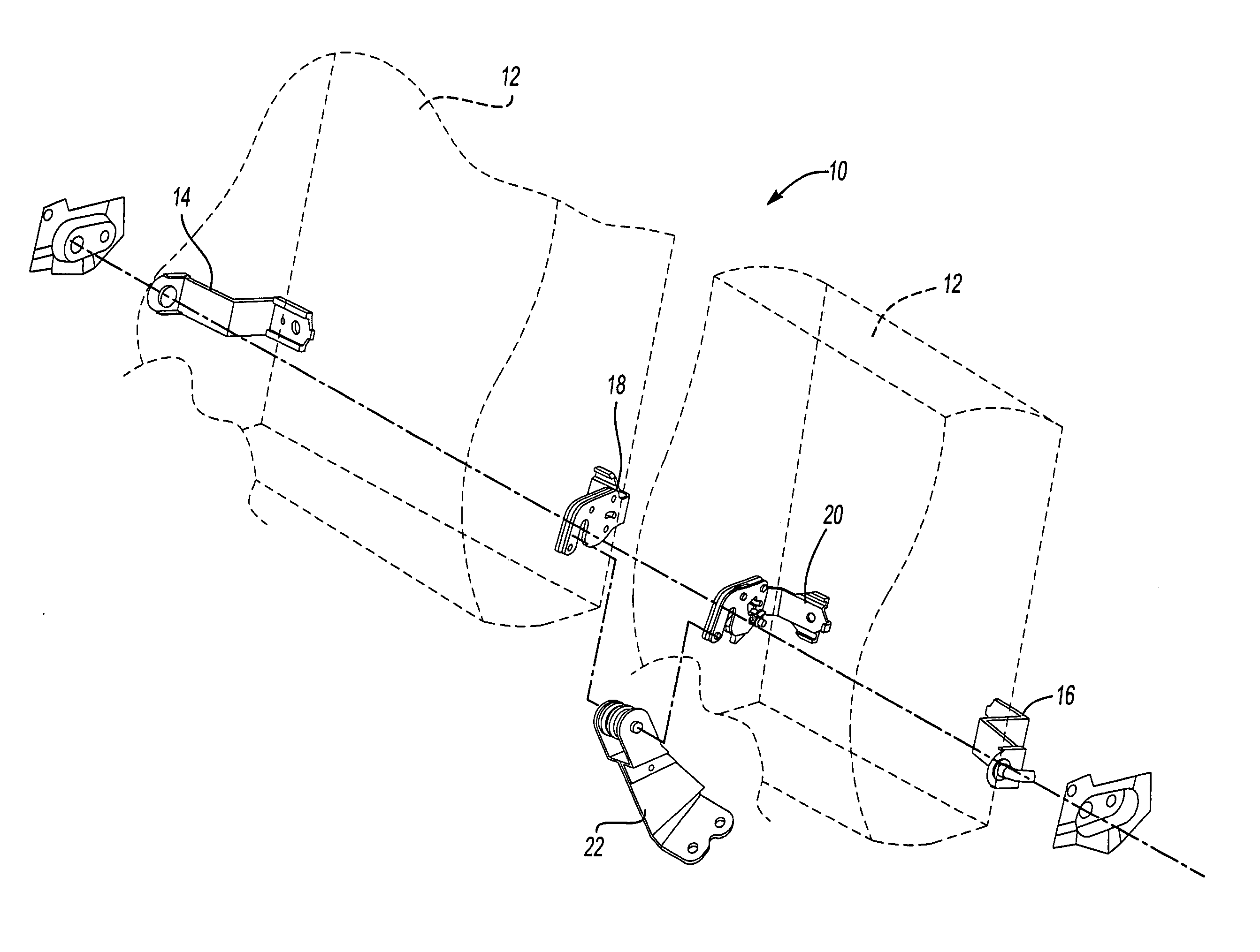
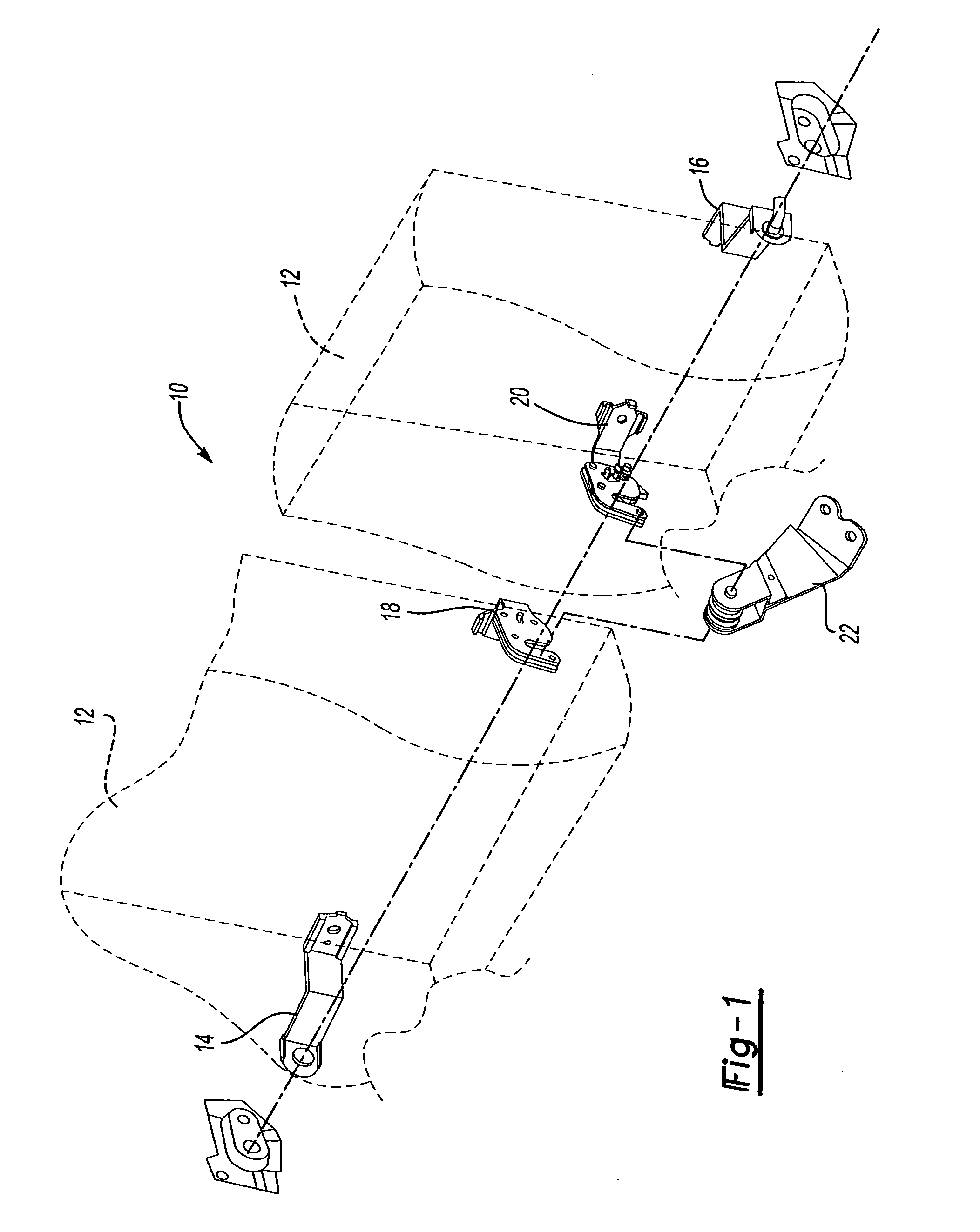
[0013]Referring now to the drawings wherein like reference numerals are used to identify identical components in the various views, FIG. 1 illustrates one embodiment of a device 10 to secure a seat back 12 to a vehicle having a first and second outer hinge 14, 16, a first and second inner hinge 18, 20, and a base 22. The first and second outer hinges 14, 16 are generally configured to secure a seat back 12 to a vehicle. The first and second inner hinges 18, 20 are generally configured to cooperate with the base 22 to further secure a seat back 12 to a vehicle.

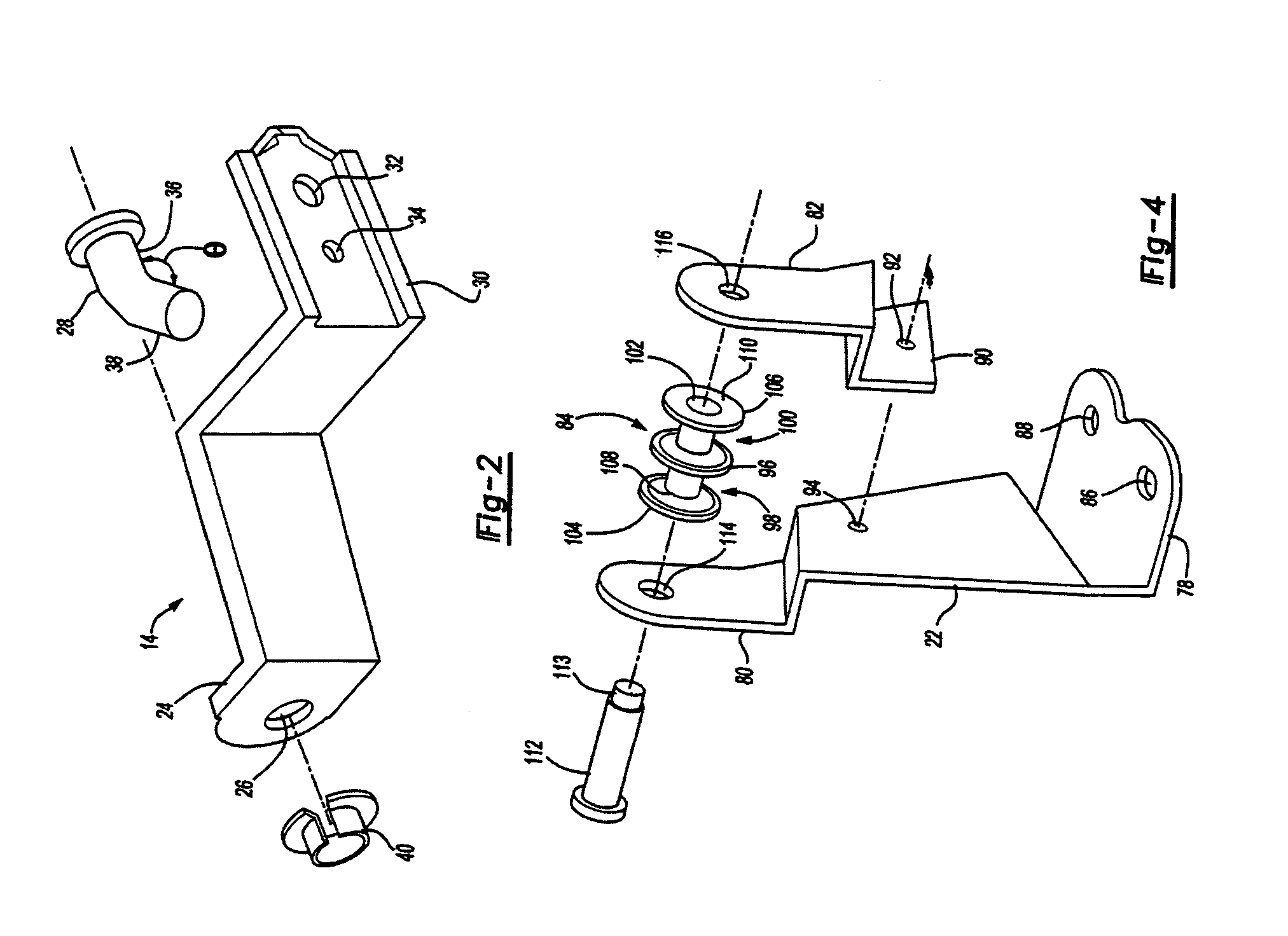
[0014]Referring now to FIG. 2, the first outer hinge 14 has a first flange 24 having a bore 26 through which a pin 28 is inserted. The second flange 30 includes a bore 32 through which fasteners such as screws, bolts, pins and other equivalents can be inserted to secure the hinge 14 to a vehicle. The second flange 30 can also include a bore 34 that can be used by a line worker to manipulate any tooling needed in the assembly pr...


PUM


Abstract

A device is provided for securing a seat back to a vehicle. The device includes a base that is mounted on the floor of the vehicle. The base includes a spool that can be partitioned to create separate areas upon which the seat backs can be mounted. The device also includes a first hinge that is mounted on the outer side of the seat back. The first hinge can include a pin that is comprised of two portions. The first portion of the pin extends normal to the seat back, and the second portion of the pin extends at an angle therefrom. The device further includes a second hinge that is mounted on the inner side of the seat back. The second hinge includes a slot that is configured to cooperate with the spool of the base mounted on the floor to attach the seat back to the vehicle.

Description

BACKGROUND OF THE INVENTION[0001]1. Field of the Invention[0002]The present invention relates to hinges for a folding seat back and, more particularly, hinges having an angularly shaped pin and / or a partitioned spool for a rear seat back.[0003]2. Description of the Prior Art[0004]Generally, the installation of seat back frames to a vehicle is a difficult and costly process. In a typical installation process, a center pivot bracket is bolted to the floor of the vehicle and the seat back frames are then bolted to the bracket for pivoting. Because this assembly process takes an undesirably long period of time to accomplish, the process imposes an additional manufacturing cost. Moreover, the installation of a rear seat poses an ergonomic burden on the line worker. In a typical seat back installation, the seat trim and the foam portions can obstruct the view of the line worker, which results in a blind attachment assembly operation. This blind attachment can substantially slow the vehicl...

Claims


Application Information

Patent Timeline
Patent Type & Authority Patents(United States)
IPC IPC(8): B60N2/20B60N2/22
CPCB60N2/2245B60N2/20
Inventor RHEE, QUE-WHANGOLIVER, JASON ROY
Owner TOYOTA MOTOR CO LTD
Learn More