Electrical connector

a technology of electrical connectors and connectors, applied in the direction of electrical devices, printed circuits, coupling contact members, etc., can solve the problems of insufficient stability of contact between plugs and receptacle contacts, adversely affecting the performance of electric circuits to be connected to electrical connectors, and the above problems are particularly acute, so as to achieve superior contact stability

Active Publication Date: 2006-08-01
DDK LTD +1
View PDF32 Cites 21 Cited by
  • Summary
  • Abstract
  • Description
  • Claims
  • Application Information

AI Technical Summary

Benefits of technology

[0006]It is an object of the invention to provide an electrical connector which eliminates the disadvantages of the prior art descried above and which is particularly superior in stability of contact between receptacle and plug connectors by reasonably forming the shape of at least one of front end portions of the receptacle and plug contacts.
[0014]In a preferred embodiment of the invention, the first and second through-holes of the receptacle and plug connectors have cross-sectional shapes corresponding to the branched contact portions of the front end portions of the respective contacts, making it possible to fit the staggered branched contact portions into the first and second through-holes of the receptacle and plug connectors, respectively.
[0016](1) According to the invention, by properly forming the shape of at least one of front end portions of the plug contacts and the receptacle contacts, it becomes possible to provide an electrical connector superior in stability of contact between the receptacle contacts and the plug contacts.
[0017](2) According to the invention, moreover, the three branched contact portions are provided on each of front end portions of the plug contacts and the receptacle contacts, while the front end portions of the plug and receptacle contacts are adapted to be coupled and engaged with each other, thereby more improving the stability of contact between the plug and receptacle contacts.

Problems solved by technology

Therefore, sufficient stability of contact between the plug and receptacle contacts would not be obtained.
If such a stability of the contact between the plug and receptacle contacts could not be obtained, electric current will be concentrated at any contact points so that the contacts would tend to be overheated with the concentrated current.
The heat resulting from the overheated contacts would be transmitted to other connector members to adversely affect even the performance of electric circuits to be connected to the electrical connector.
Accordingly, the above problems would be particularly acute in this case.

Method used


Image

  • Electrical connector
  • Electrical connector
  • Electrical connector

Examples


Embodiment Construction

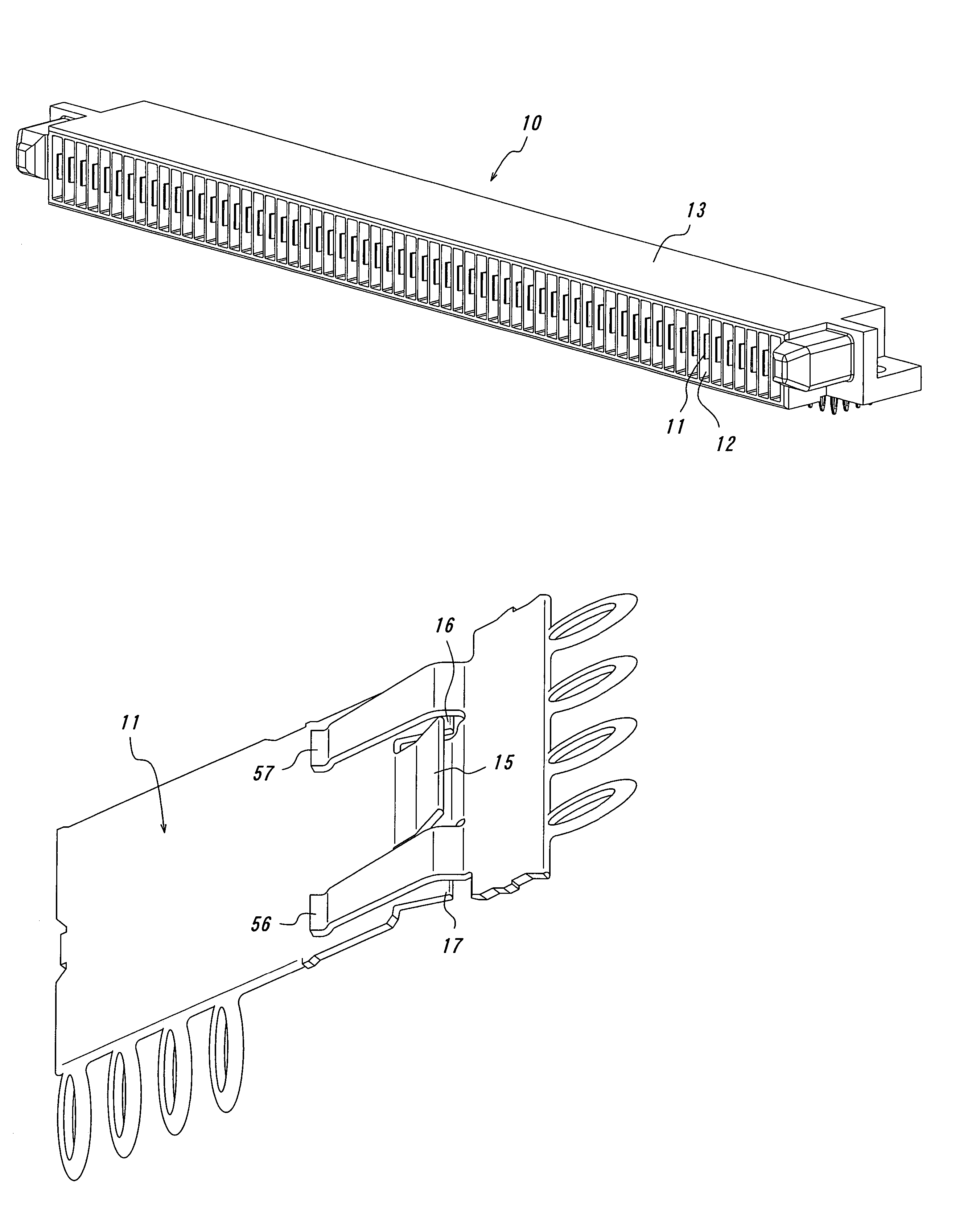
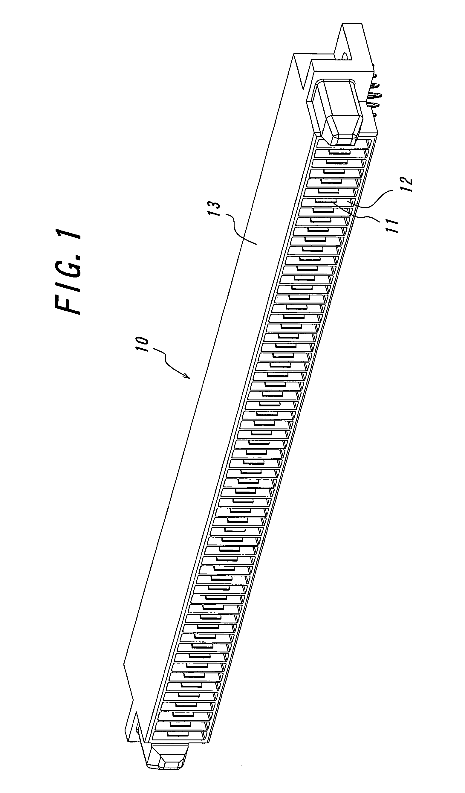
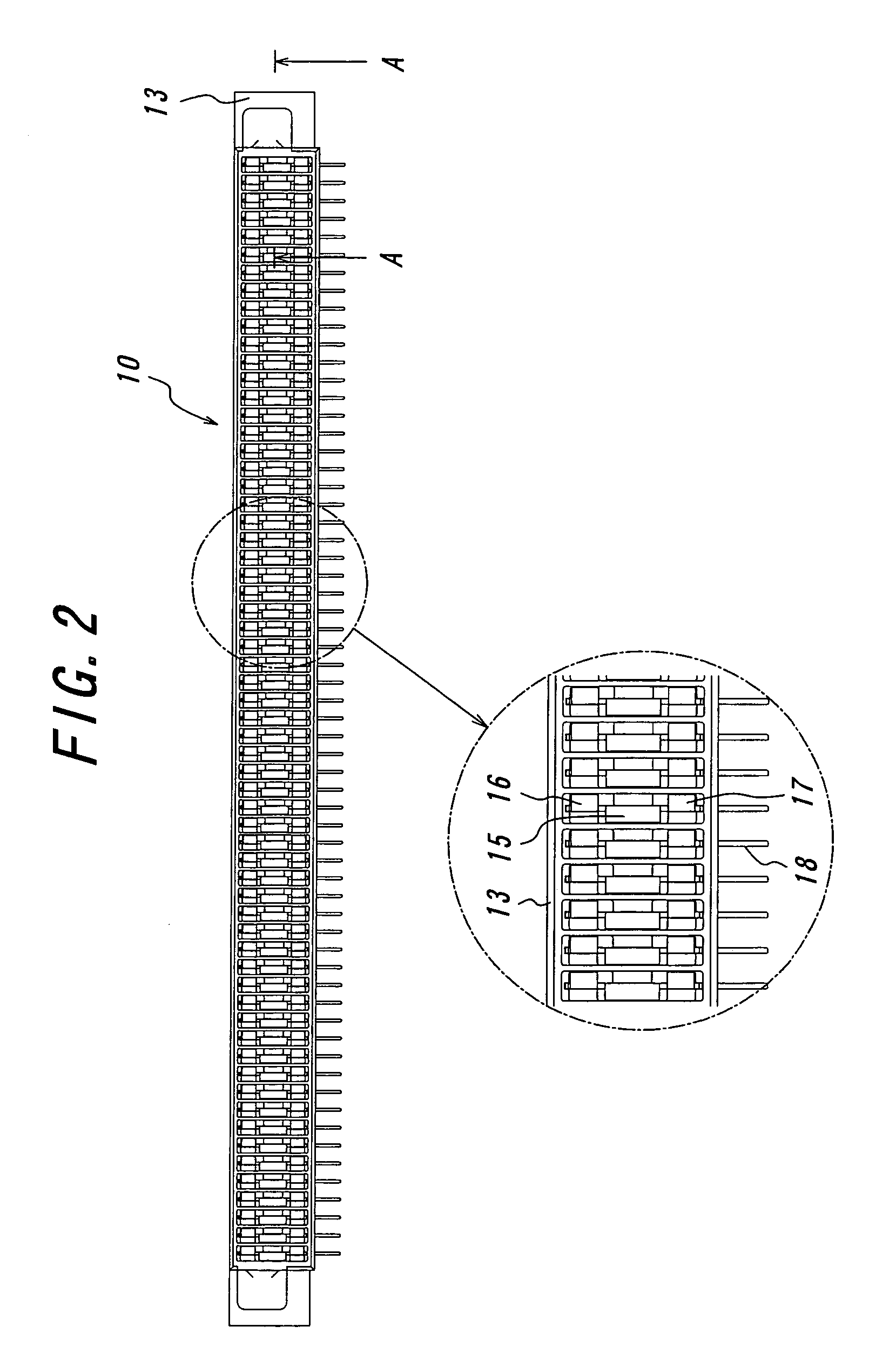
[0029]Preferred embodiments for carrying out the present invention will be explained with reference to the drawings hereinafter. FIGS. 1 and 2 are a perspective and a front view of a receptacle connector constructing a typical electrical connector according to the present invention. FIG. 3 is a sectional view of the receptacle connector taken along the line A—A in FIG. 2. FIG. 4 is a perspective view of a receptacle contact used in the receptacle connector shown in FIG. 1. FIGS. 5 and 6 are a perspective and a front view of a plug connector constructing the typical electrical connector according to the present invention. FIG. 7 is a sectional view of the plug connector taken along the line B—B in FIG. 6. FIG. 8 is a perspective view of a plug contact used in the plug connector shown in FIG. 5. FIG. 9 is a perspective view illustrating the receptacle and plug contacts in a connected state.

[0030]The electrical connector according to the invention comprises the receptacle connector 10 ...


PUM


Abstract

The electrical connector includes a receptacle connector 10 and a plug connector 50. The receptacle connector includes a first housing 13 made of an insulating material having plate-shaped receptacle contacts 11 made of a conductive material and formed with first through-holes 12 for accommodating the plate-shaped receptacle contacts. The plug connector includes a second housing 53 made of an insulating material having plate-shaped plug contacts 51 made of a conductive material and formed with second through-holes 52 for accommodating the plate-shaped plug contacts. At least three branched contact portions 55 to 57 and 15 to 17 are provided in staggered form on both front end portions 54 and 14 of the plug contact and the receptacle contact. With this construction, the electrical connector is superior in stability of contact between the receptacle and plug contacts.

Description

CROSS-REFERENCE TO RELATED APPLICATIONS[0001]This application claims priority from Japanese Patent Application No. 2004-229438, filed Aug. 5, 2004, which is incorporated by reference in its entirety.BACKGROUND OF THE INVENTION[0002]This invention relates to an electrical connector including a receptacle connector and a plug connector and superior in stability of contact between the receptacle and plug connectors.[0003]In prior art electrical connectors, generally, plug contacts are blade-shaped in cross-section as shown in, for example, Japanese Patent Application Opened No. 2003-142,213 or pin-shaped in cross-section as shown in, for example, Japanese Patent Application Opened No. H10-189,105 (1998). Receptacle contacts opposite to the plug contacts each have a pair of cantilevered beams exerting inwardly directing springy forces. When connecting the connectors, the blade-shaped or pin-shaped plug contacts are inserted between beams of the receptacle contacts to achieve electrical ...

Claims


Application Information

Patent Timeline
Patent Type & Authority Patents(United States)
IPC IPC(8): H01R12/00
CPCH01R12/7088H01R13/02
Inventor MISAWA, SHINRIFUKAZAWA, TAKEKIMIMA, HISATOMOSEKINO, YUICHI
Owner DDK LTD
Why Eureka
Try Eureka