Pivoting joint infusion system with seal

a joint infusion and seal technology, applied in the direction of filtration separation, catheter, separation process, etc., can solve the problems of leakage connections and inefficient ways

Inactive Publication Date: 2006-08-01
VICENTRA +1
View PDF44 Cites 112 Cited by
  • Summary
  • Abstract
  • Description
  • Claims
  • Application Information

AI Technical Summary

Problems solved by technology

Most of these prior art systems are plagued with leaking connections and inefficient ways to allow the patient to disconnect the fluid connector from the base without a backflow of fluid from the patient through the base and back into the environment.

Method used


Image

  • Pivoting joint infusion system with seal
  • Pivoting joint infusion system with seal
  • Pivoting joint infusion system with seal

Examples


Embodiment Construction

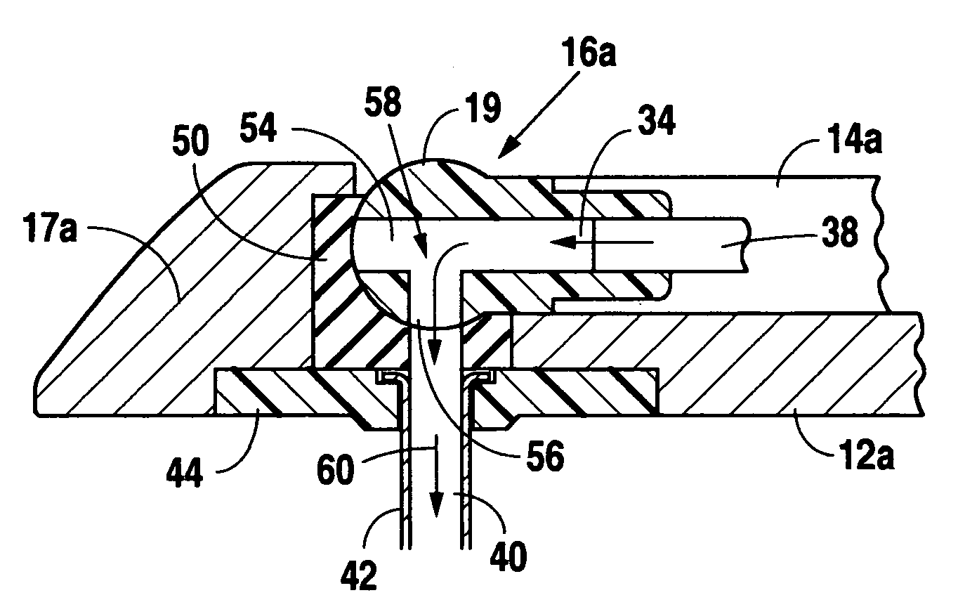
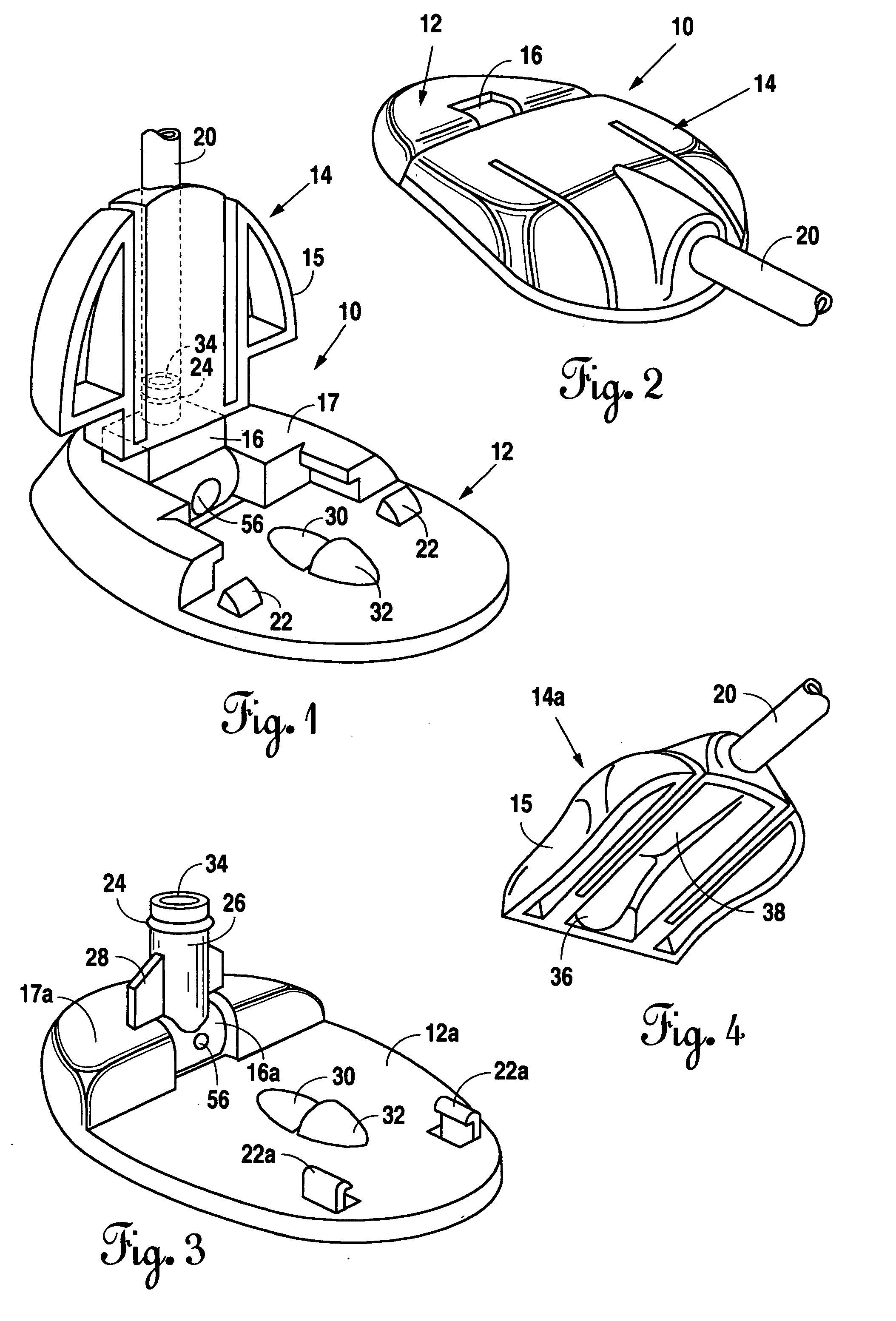
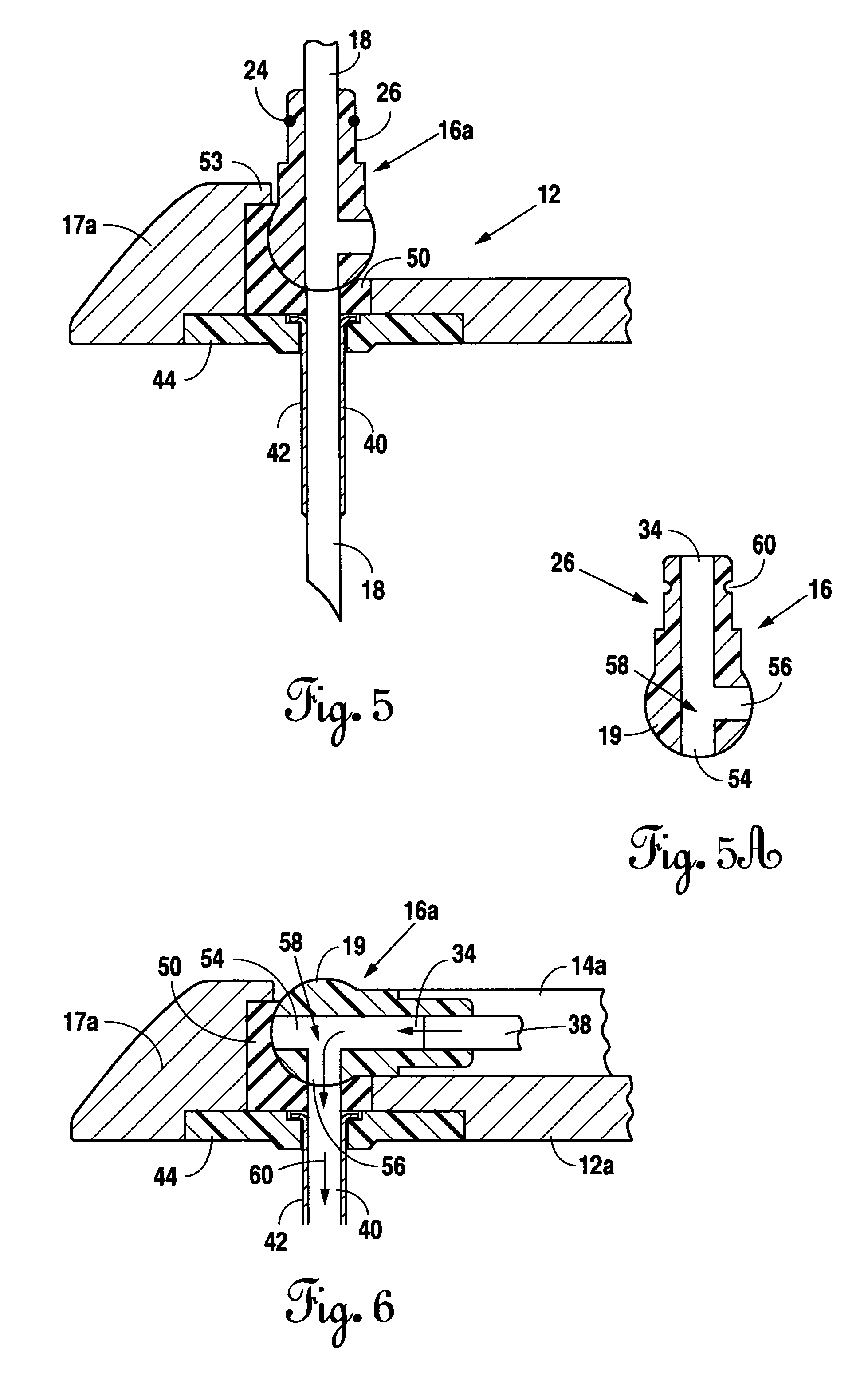
[0015]FIG. 1 is a perspective view of the infusion system 10 of the present invention. In FIG. 1, the main infusion unit 12 is shown with the fluid connector assembly 14 attached to the rotating pivot joint member 16. The joint member 16 is rotatably attached to the housing 17 of unit 12. The emplacement needle 18 (FIG. 5) has been withdrawn and the connector assembly is still in an upright or vertical position. Therapeutic fluid from a remote source (not shown but well known in the art) such as a wall or rack hung bottle or plastic fluid bag may be delivered through delivery tube 20 to the connector assembly 14 and into the patient. However, the preferred procedure is for the needle to be withdrawn and the joint member 16 slightly rotated downwardly to misalign the emplacement channel 54 (FIG. 5A) and the injection channel 40. This will prevent or significantly avoid a backflow of patient fluids as will be discussed below. The connector assembly 14 is then attached to the joint mem...


PUM

PropertyMeasurementUnit
axial rotationaaaaaaaaaa
approach angleaaaaaaaaaa
coefficients of frictionaaaaaaaaaa

Abstract

An infusion system for delivery of therapeutic fluids from a remote source into a patient's body. The system has an infusion assembly, a rotating pivot joint member, a fluid connector assembly, and a sealing assembly retained within the infusion assembly between the housing of the infusion assembly and the rotating pivot joint member. The seal reduces leakage of fluids. The rotating joint may be pivoted to three distinct positions to allow for emplacement on the patient, delivery of the therapeutic fluid to the patient, and protected, sealed closure of the fluid channels to avoid patient fluid backflow.

Description

[0001]This application is a continuation-in-part application of U.S. patent application Ser. No. 09 / 896,149, filed Jun. 29, 2001, now U.S. Pat. No. 6,579,267, issued Jun. 17, 2003, which claims priority to U.S. Provisional Application No. 60 / 259,971, filed Jan. 5, 2001, all of which are incorporated herein by reference for all purposes.FIELD OF THE INVENTION[0002]The present invention relates to an improved system for subcutaneous delivery of fluid to a patient. More particularly, the present invention relates to an infusion system having an improved sealing subsystem cooperating with a rotating pivot joint member that delivers the fluid from a remote source to a delivery cannula of the main infusion assembly of the system.BACKGROUND OF THE INVENTION[0003]Prior art infusion sets or systems provide numerous ways for engaging a fluid connector to a base to deliver a therapeutic fluid subcutaneously to a patient. Most of these prior art systems are plagued with leaking connections and ...

Claims


Application Information

Patent Timeline
Patent Type & Authority Patents(United States)
IPC IPC(8): A61M5/32A61K9/22A61M5/142A61M5/158
CPCA61M5/14244A61M5/158A61M39/02B01D39/163B01D2239/0663A61M2005/14252A61M2005/1581A61M2005/1587B01D2239/0208B01D2239/0216B01D2239/0225B01D2239/0233B01D2239/0414B01D2239/045B01D2239/0471B01D2239/0636B01D2239/0659A61M5/14248
Inventor LYNCH, GEORGE R.BRANDENBURG, ALLEN E.NELSON, ANDREWPETITJEAN, GILLES
Owner VICENTRA
Why Eureka
Try Eureka