

Security system
a technology for security systems and radio waves, applied in burglar alarm short radiation actuation, instruments, measurement devices, etc., can solve the problems of high wiring cost and difficulty in emitted radio waves over a wide area, and achieve the effect of not affecting the building and being easy to install
- Summary
- Abstract
- Description
- Claims
- Application Information
AI Technical Summary
Benefits of technology
Problems solved by technology
Method used
Image

Examples
first embodiment
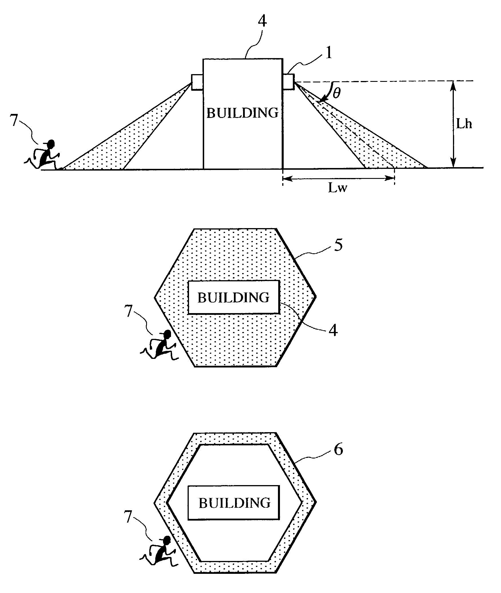
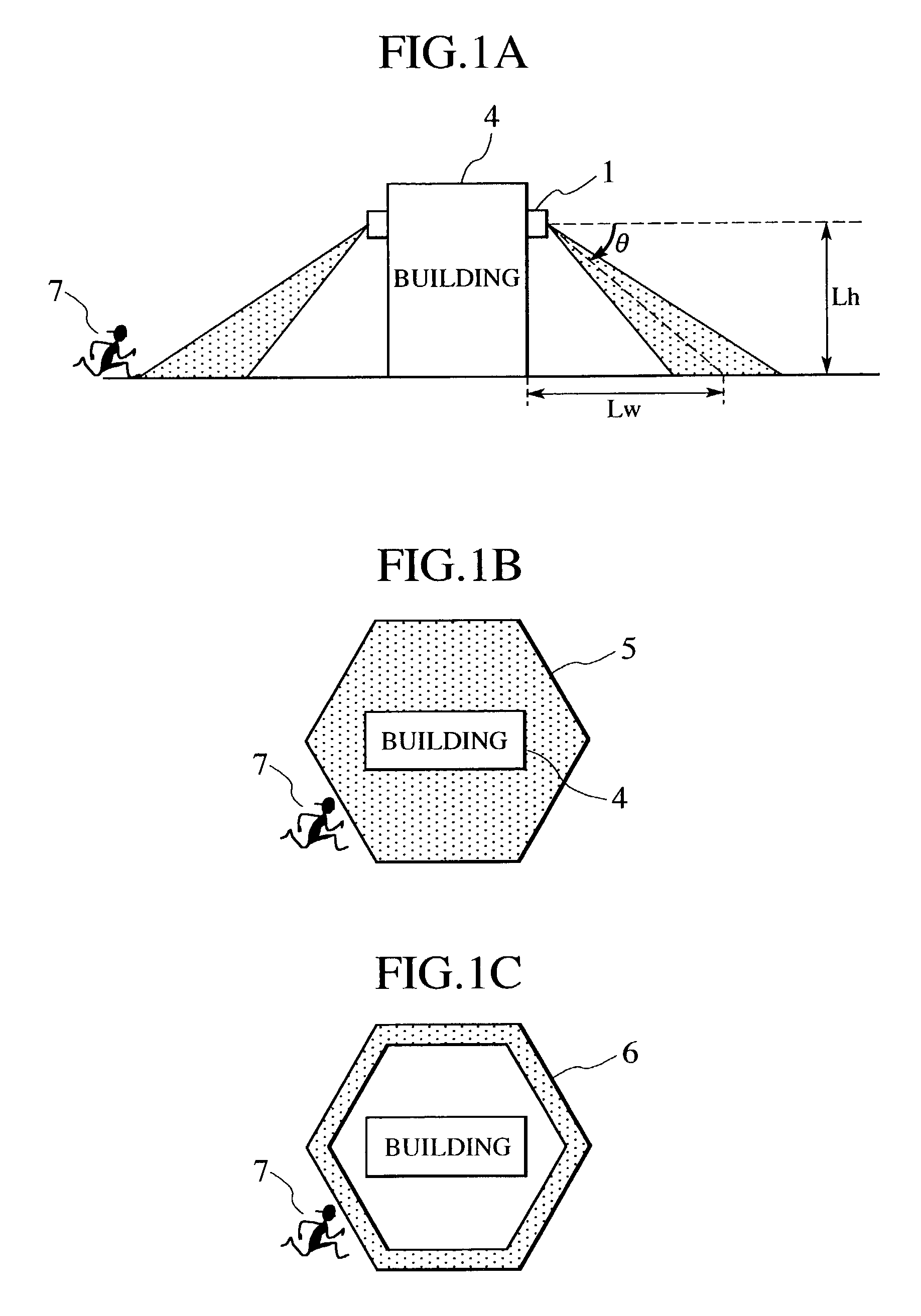
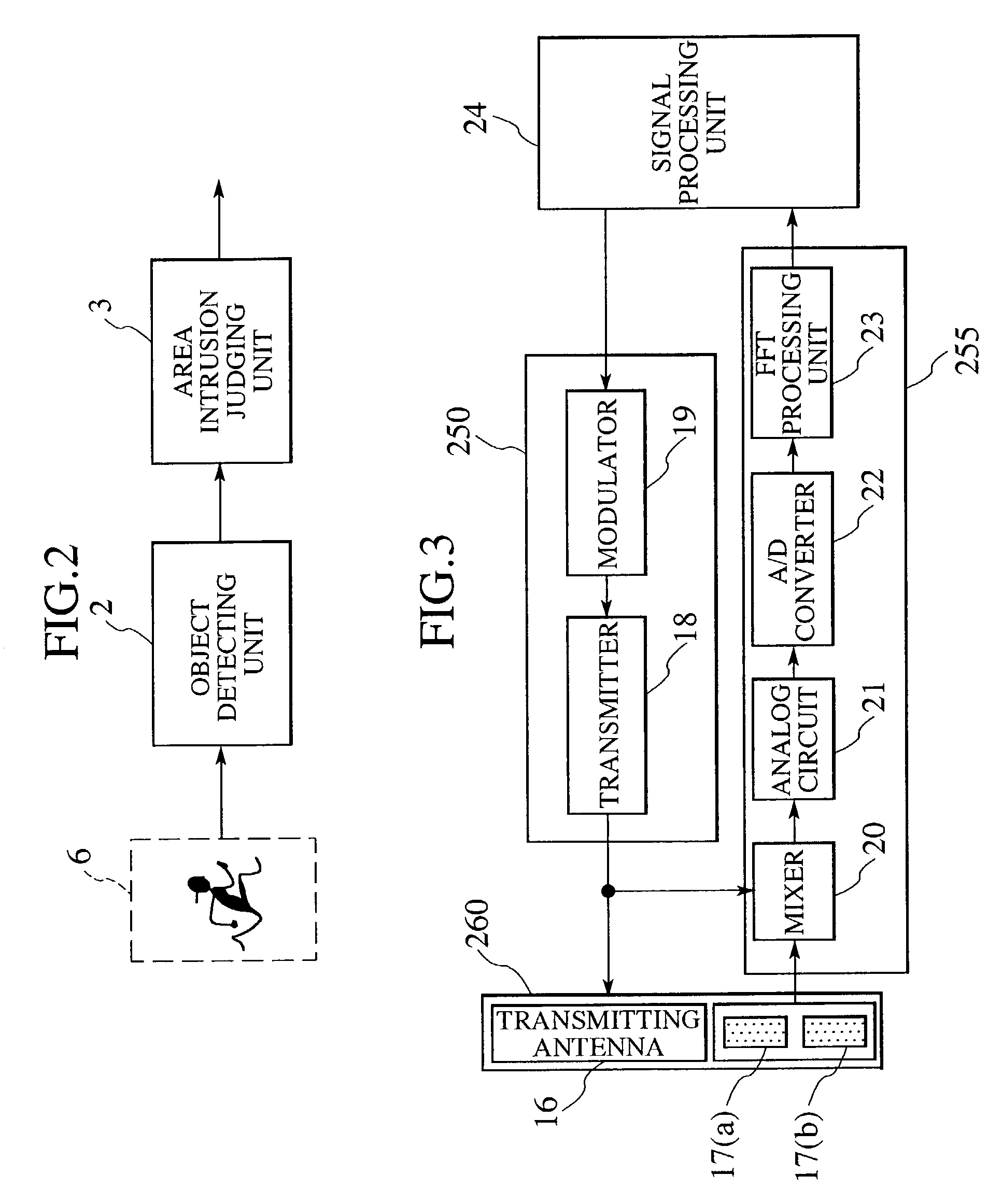
[0025]A first embodiment is based on a security system which monitors an object in an area within a predetermined range around a building, and relates to a method in which object detecting devices 1 are installed on the building and thereby a judgment is made as to whether or not a detected object will intrude into the area. FIG. 2 illustrates the configuration of this embodiment. The configuration comprises an object detecting unit 2 for detecting an object, and an area intrusion judging unit 3 for judging whether or not the detected object will intrude into the predetermined area. This embodiment will be described using a radar device as an object detecting device 1 capable of calculating relative velocity to the object and its position.
[0026]A method in which the radar device measures the relative velocity and the distance will be described with reference to FIG. 3. The radar device comprises a transmitting unit 250 which modulates a radar wave and transmits the modulated radar w...
second embodiment
[0037]A second embodiment exemplifies a method for placing the object detecting device 1 and the configuration of the object detecting device 1. As is the case with the first embodiment, the second embodiment will be described using a radar device as the object detecting device 1 capable of calculating the relative velocity to the object and its position.
[0038]FIG. 7A illustrates a method in which the radar devices are installed in a multidirectional manner so as to cover 360°. According to this method, because the plurality of radar devices are installed in a multidirectional manner, one pole structure can cover 360° around the building as a detection area. A position and an emitting angle θp of each radar device can be calculated using the means similar to that of the first embodiment. FIG. 7B illustrates the emission area 6 of a radio wave, which is viewed from the top of the building; in this figure, six wide-angle antennas, each of which has a beam angle of 60°, are used. When ...
third embodiment
[0039]A third embodiment is based on the assumption that a security system capable of the following is used: monitoring a predetermined area from a building to track an object in the area; and thereby predicting whether or not the object will intrude into the building. The third embodiment relates to a method in which the object detecting device 1 is installed on a wall surface of the building, an area around the building is monitored in respective planes thereof to track a detected object, and thereby whether or not the object will intrude into the building is predicted. FIG. 8 illustrates the configuration of this embodiment. The configuration comprises the object detecting unit 2 for detecting an object, and the building intrusion predicting unit 11 for predicting whether or not the detected object will intrude into the building.
[0040]FIG. 9A illustrates an example in which the radar device is installed on the side surface of the building and a radio wave is emitted in parallel w...
PUM
 Abstract
Description
Claims
Application Information