Non-ferrous surge biasing coil having multiple pairs of coils positioned at angles to one another

Active Publication Date: 2006-08-01
ELDER KENNETH M
View PDF11 Cites 3 Cited by
  • Summary
  • Abstract
  • Description
  • Claims
  • Application Information

AI Technical Summary

Benefits of technology

[0021]The present invention is also used with data communication line circuits, wherein multiple stage surge suppressors are

Problems solved by technology

Prior art surge elements are constructed in limited configurations and have limited surge handling capabilities.
Unfortunately, due to differences in the individual surge elements, it is difficult to bias the current through the multiple stage surge elements.
In fact, it is quite typical that the surge current is unequal throughout the multiple surge elements thereby causing an insignificant improvement in current handling as that compared to individual surge elements capable of handling the surge or transient on its own.
However, the aforementioned prior art devices have many inherent disadvantages which are not easily overcome.
However, some devices, employing series coils or resistors, conduct normal line current but experience heating during normal line current carrying conditions.
This is undesirable.
However, this is also undesirable.
However, the use of very large coils can be expensive and be a waste of valuable, limited space; again achieving an undesirable result.
Unfortunately, in AC electrical systems, the ferrous coil reacts to the changes in current, thereby creating unwanted heat as in the large coil configurations.
This results in the ferrous coil limiting current passing through the circuit as well as limiting the actual size of the coil that can be used.
Unwanted heat and the actual overheating of the coils is a big problem in the protection of electronic circuits from overvoltages and surge currents.
This of course can cause insufficient suppression capability for a parti

Method used


Image

  • Non-ferrous surge biasing coil having multiple pairs of coils positioned at angles to one another
  • Non-ferrous surge biasing coil having multiple pairs of coils positioned at angles to one another
  • Non-ferrous surge biasing coil having multiple pairs of coils positioned at angles to one another

Examples


Example

[0030]Throughout the following detailed description, the same reference numerals refer to the same elements in all figures.

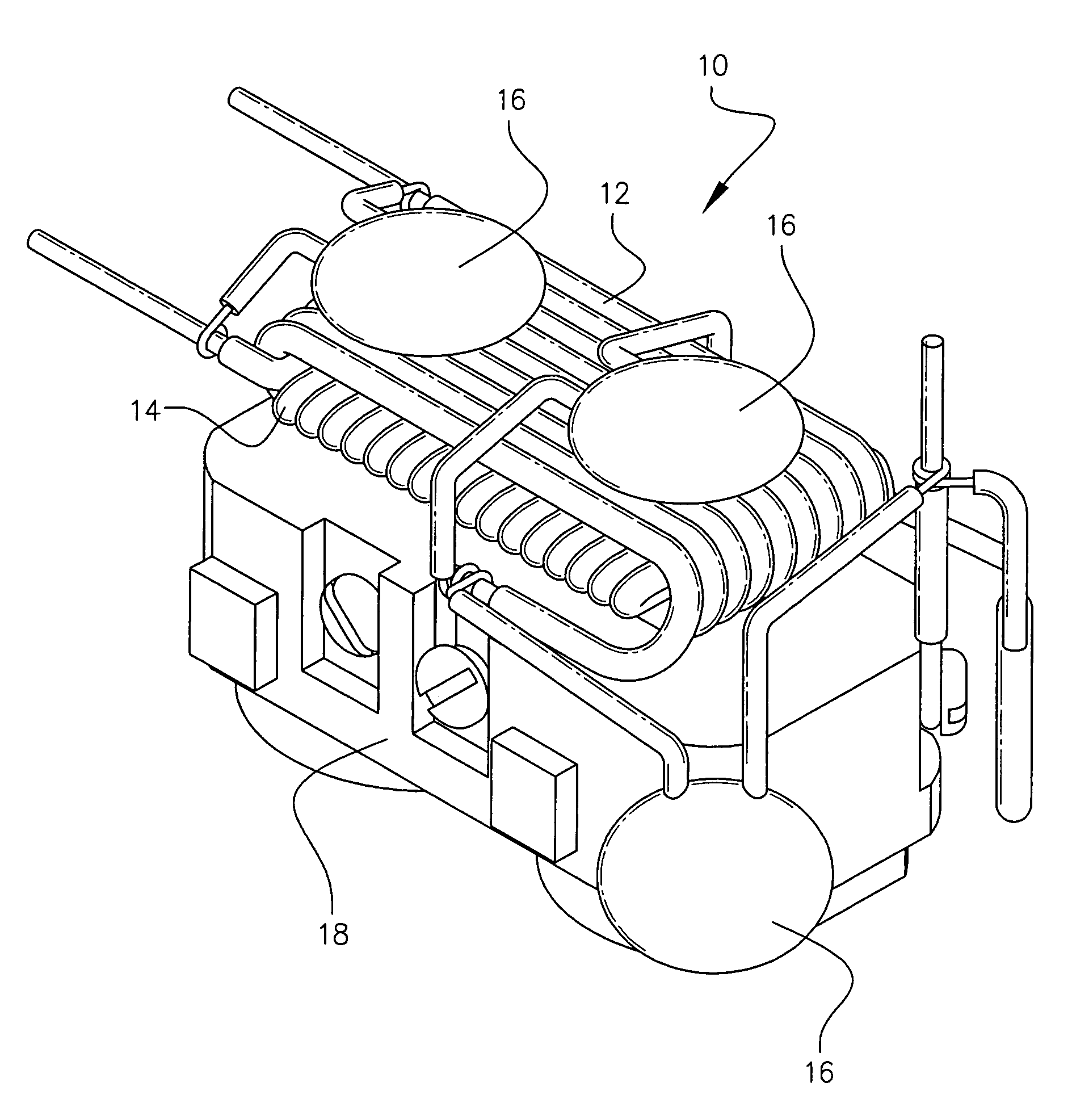
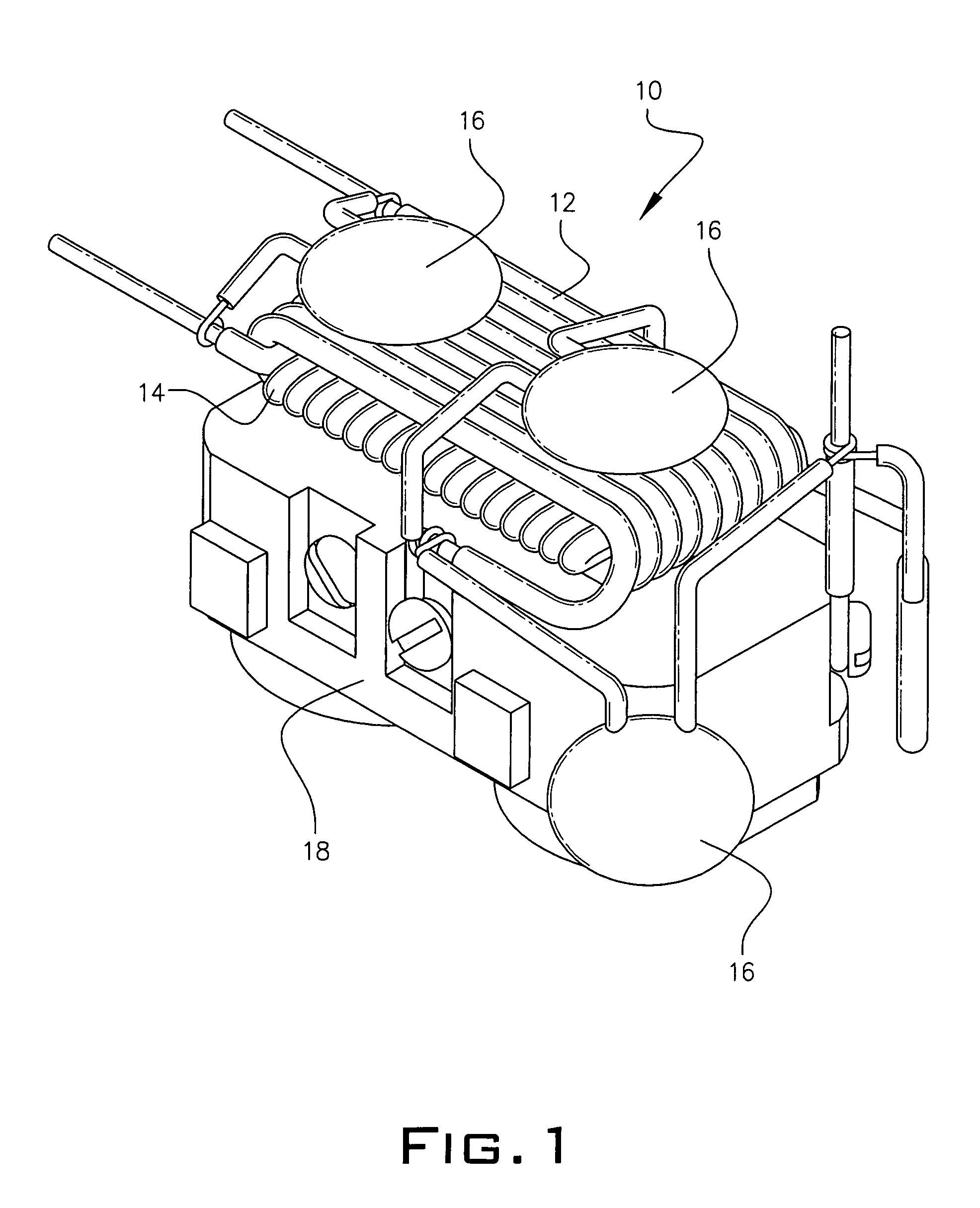
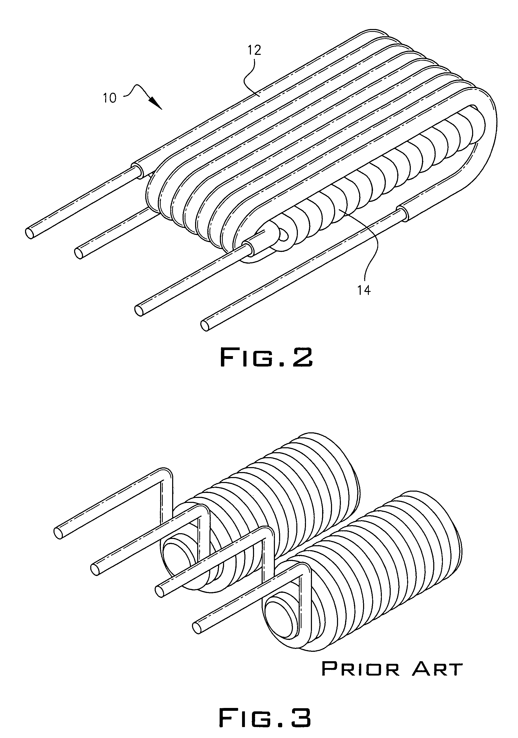
[0031]Referring to FIG. 1, a preferred embodiment of the present invention is shown. Therein, surge suppressor device 10 includes a first winding 12 and a second winding 14 such that second winding 14 is sandwiched in between (surrounded by) first winding 12. It is noted that suppressor 10, as shown in FIG. 1, discloses that first and second windings, 12 and 14 respectively, are positioned at a generally perpendicular angle (ninety degrees), what is considered the preferred embodiment. However, nothing herein limits suppressor 10 from having windings 12 and 14 positioned at angles different from that of the preferred embodiment. In fact windings 12 and 14 can be positioned at varying angles from that of 90 degrees so long as the windings are not positioned in a parallel relationship. It is further noted that suppressor 10 includes a plurality of metal oxide vari...


PUM


Abstract

A surge suppression device includes a first and second coil positioned in close proximity to one another such that the windings of each coil are disposed at an angle thereto. In a preferred embodiment, the coils are disposed such that the windings of each coil are placed at a right angle (90 degrees) to one another. However, angles of varying degree can be employed. Varying configurations of the coil winding placement include a “sandwiched” type configuration, a “one on the top of the other” configuration as well as an intertwined configuration. Each embodiment employs additional surge elements such as metal oxide varistors (MOVs). It is unnecessary to employ any ferrous material core for any of the coils used in the novel device of the present invention.

Description

PRIOR APPLICATIONS[0001]This is a non-provisional utility patent application which bases priority on provisional patent application 60 / 390,894, filed on Jun. 25, 2002.BACKGROUND OF THE INVENTION[0002]1. Field of The Invention[0003]This invention relates to a biasing coil used in multi-stage surge suppression and transient protection. More particularly, it relates to a non-ferrous biasing coil used in surge suppression and transient protection of electronic devices and data communication lines wherein multiple coils are employed in close proximity to one another, positioned at angles, and dual-wound.[0004]2. Background of the Prior Art[0005]Inductive-capacitive filter biasing coils used for the purpose of surge protection and surge suppression systems are known in the prior art. FIG. 3 of the drawings illustrates that a pair of biasing coils having a ferrous material core inserted within a center portion of each coil are used to offer surge protection to electronic devices and data c...

Claims


Application Information

Patent Timeline
IPC IPC(8): H02H3/08H01F17/02H01F17/06H01F27/28H04M3/18
CPCH01F17/02H04M3/18H01F27/2823H01F17/06
Inventor ELDER, KENNETH M.
Owner ELDER KENNETH M
Why Eureka
Try Eureka