Autonomous machine

Inactive Publication Date: 2006-08-01
DYSON TECH LTD
View PDF15 Cites 206 Cited by
  • Summary
  • Abstract
  • Description
  • Claims
  • Application Information

AI Technical Summary

Benefits of technology

[0018]The navigation system can be implemented entirely in hardware, in software running on a processor, or a combination of these. Accordingly, a further aspect of the present inv

Problems solved by technology

Unfortunately, relying on odometry information alone is unreliable as errors can quickly accumulate, and this can eventually lead to a complete disorientation of the machine.
Poor odometry information results in a difference between the calculated position of the machine and the actual position of the machine.
In a floor cle

Method used


Image

  • Autonomous machine
  • Autonomous machine
  • Autonomous machine

Examples


Embodiment Construction

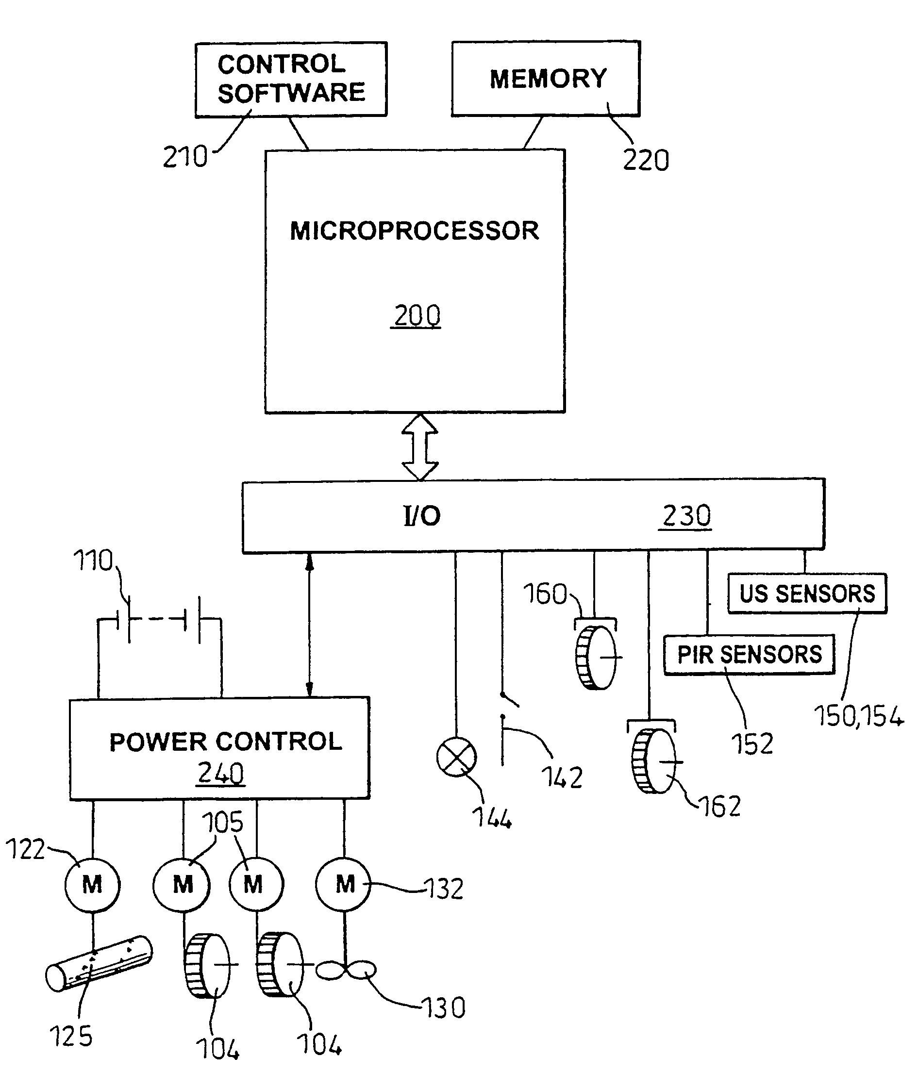
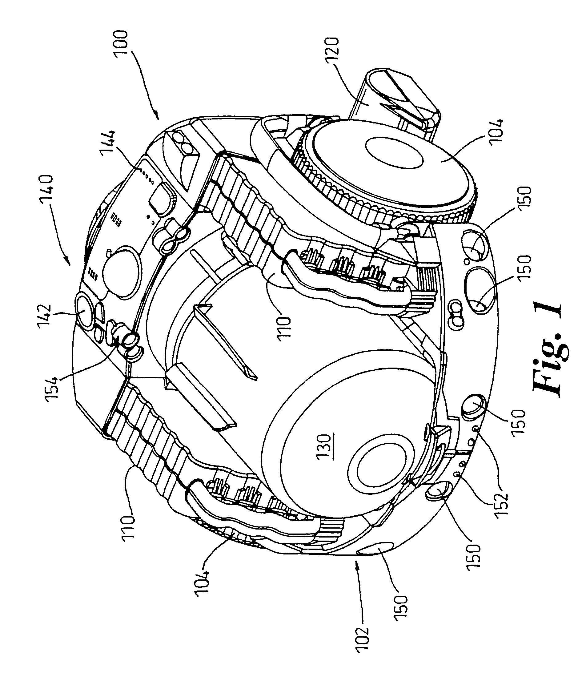
[0038]FIG. 1 of the drawings shows a robotic, or autonomous, floor cleaning machine in the form of a robotic vacuum cleaner 100.

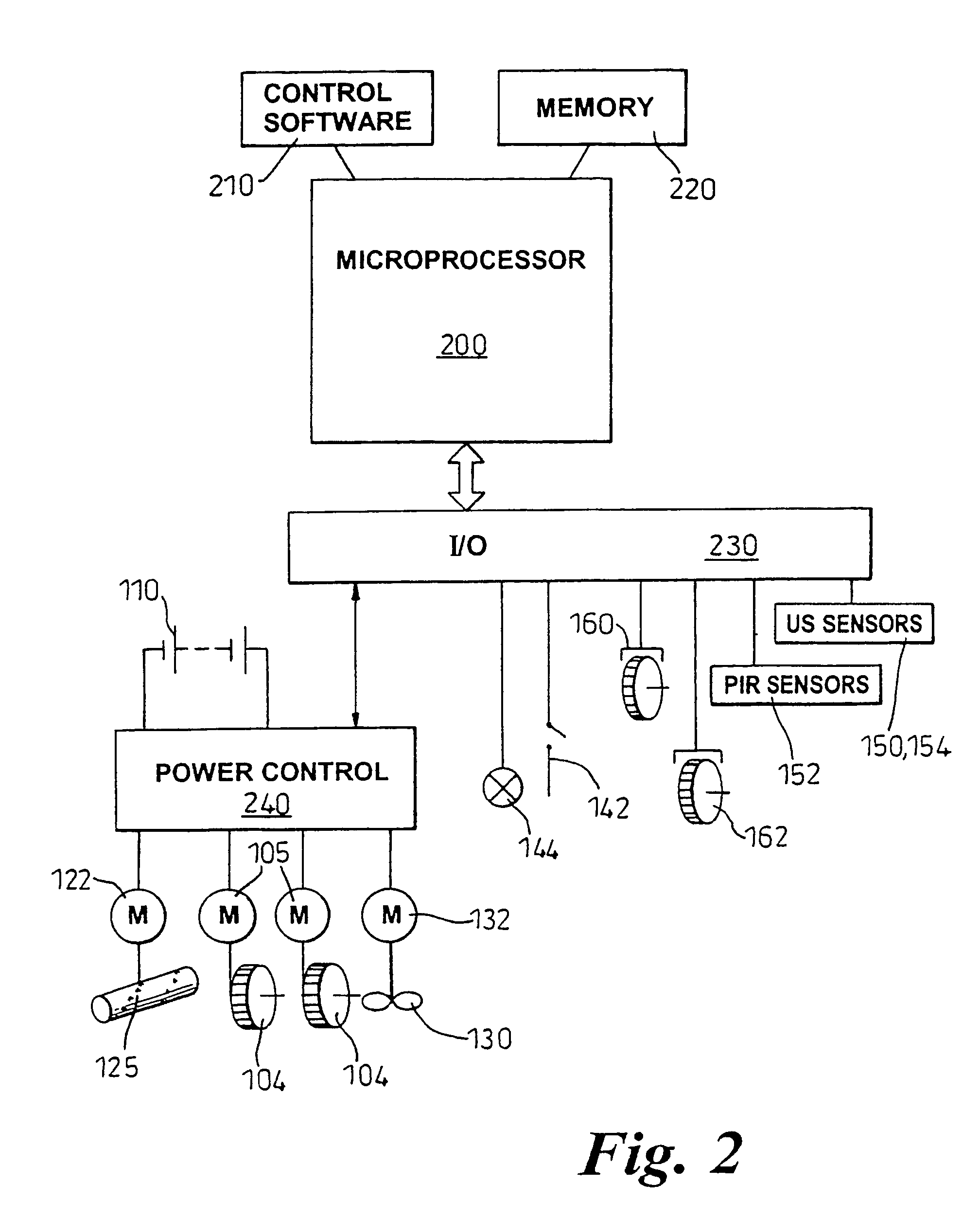
[0039]The cleaner comprises a main body or supporting chassis 102, two driven wheels 104, a brushbar housing 120, batteries 110, a dust separating and collecting apparatus 130, a user interface 140 and various sensors 150, 152, 154. The supporting chassis 102 is generally circular in shape and is supported on the two driven wheels 104 and a castor wheel (not shown). The driven wheels 104 are arranged at either end of a diameter of the chassis 102, the diameter lying perpendicular to the longitudinal axis of the cleaner 100. The driven wheels 104 are mounted independently of one another via support bearings (not shown) and each driven wheel 104 is connected directly to a traction motor which is capable of driving the respective wheel 104 in either a forward direction or a reverse direction. A full range of manoeuvres are possible by independently controlling...


PUM


Abstract

An autonomous machine is configured to explore the area in which it is located, constructing a map of the area based on information collected by the machine as the machine explores the area. The machine determines when it has returned to a previously visited position within the area. The map is corrected when the machine returns to the previously visited position, based on the knowledge that the current position and the previously visited position are the same.

Description

FIELD OF THE INVENTION[0001]This invention relates to an autonomous machine, such as an autonomous machine for cleaning a floor area.BACKGROUND OF THE INVENTION[0002]There have been various proposals to provide autonomous or robotic machines for performing duties such as cleaning or polishing a floor area or for mowing grass. In their simplest form, an autonomous machine requires a training phase during which the machine is manually led around the area in which it is to work. Following this training phase, the autonomous machine will then perform the required work as it follows the path which it stored in its memory during the training phase. Other machines may simply follow a predetermined route which is marked by means such as a cable which is buried beneath the working area.[0003]Other autonomous machines are supplied with a map of the environment in which they are to be used. The machine then uses this map to plan a route around the environment.[0004]There have also been proposa...

Claims


Application Information

Patent Timeline
IPC IPC(8): G05B19/04G05B19/18A47L9/00G05D1/02
CPCG05D1/0242G05D1/0255G05D1/0274G05D1/0272G05B2219/45098G05D2201/0208G05D2201/0203
Inventor ALDRED, MICHAEL DAVIDSHARDLOW, ANDREW MICHAEL
Owner DYSON TECH LTD
Why Eureka
Try Eureka