

Fabrication of single polarity programmable resistance structure
- Summary
- Abstract
- Description
- Claims
- Application Information
AI Technical Summary
Problems solved by technology
Method used
Image

Examples
first embodiment
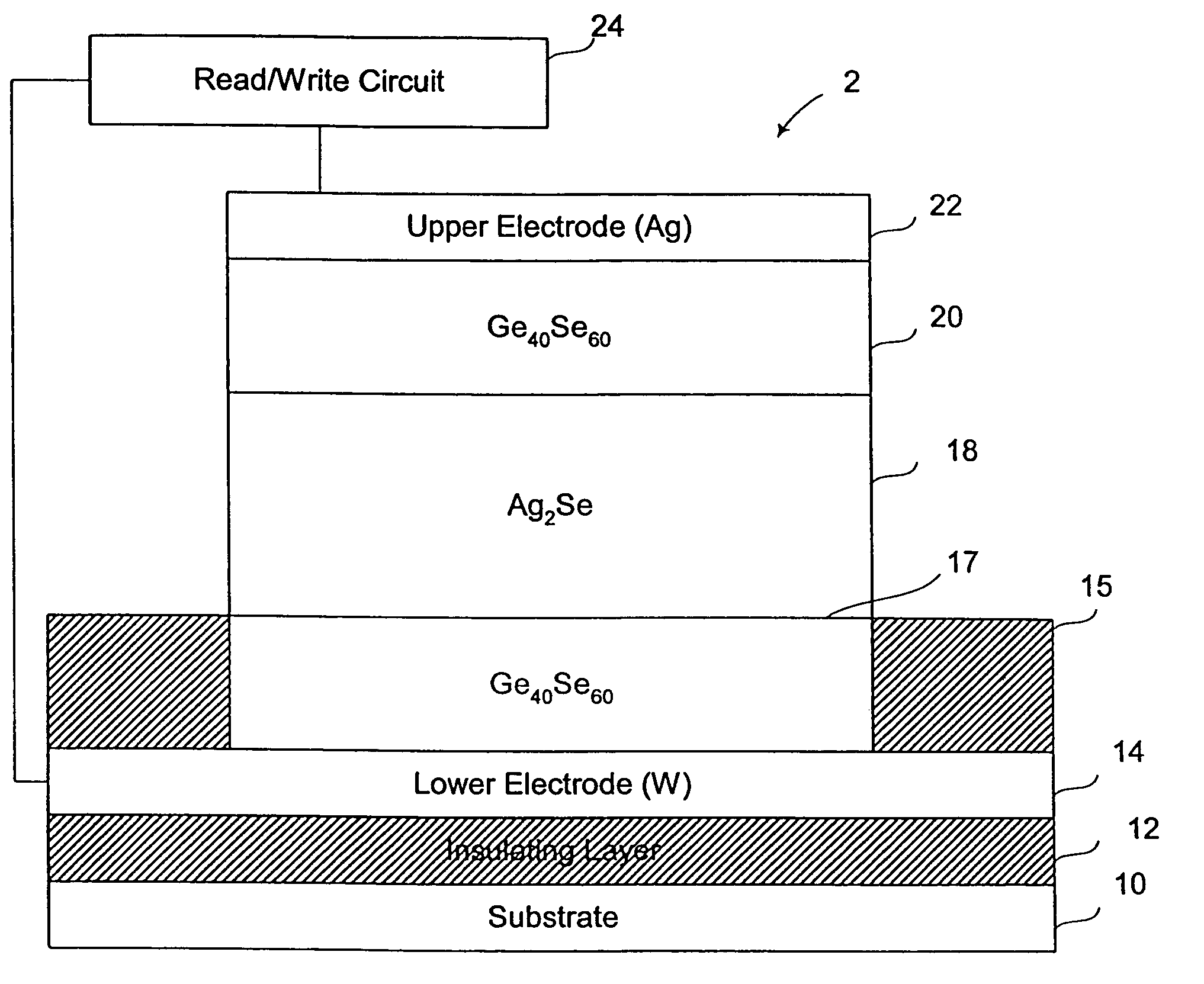
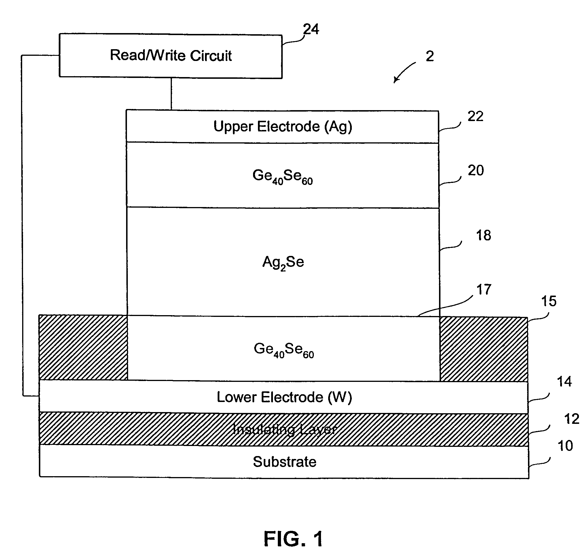
[0039]In accordance with a variation of the invention, one or more layers of a metal containing material, such as silver-selenide, may be deposited on the first chalcogenide glass layer 17. Any number of silver-selenide layers may be used. Thus, an optional second silver-selenide layer may be deposited on the first silver-selenide layer 18.
[0040]The thickness of the layers is such that the total thickness of the combined metal containing layers, e.g., silver-selenide layers, is greater than or equal to the thickness of the first chalcogenide glass layer. The total thickness of the combined metal containing layers is also greater than the thickness of the second chalcogenide glass layer. It is preferred that the total thickness of the combined metal containing layers is between about 1 to about 5 times greater than the thickness of the first chalcogenide glass layer and accordingly between about 1 to about 5 times greater than the thickness of the second chalcogenide glass layer. It ...
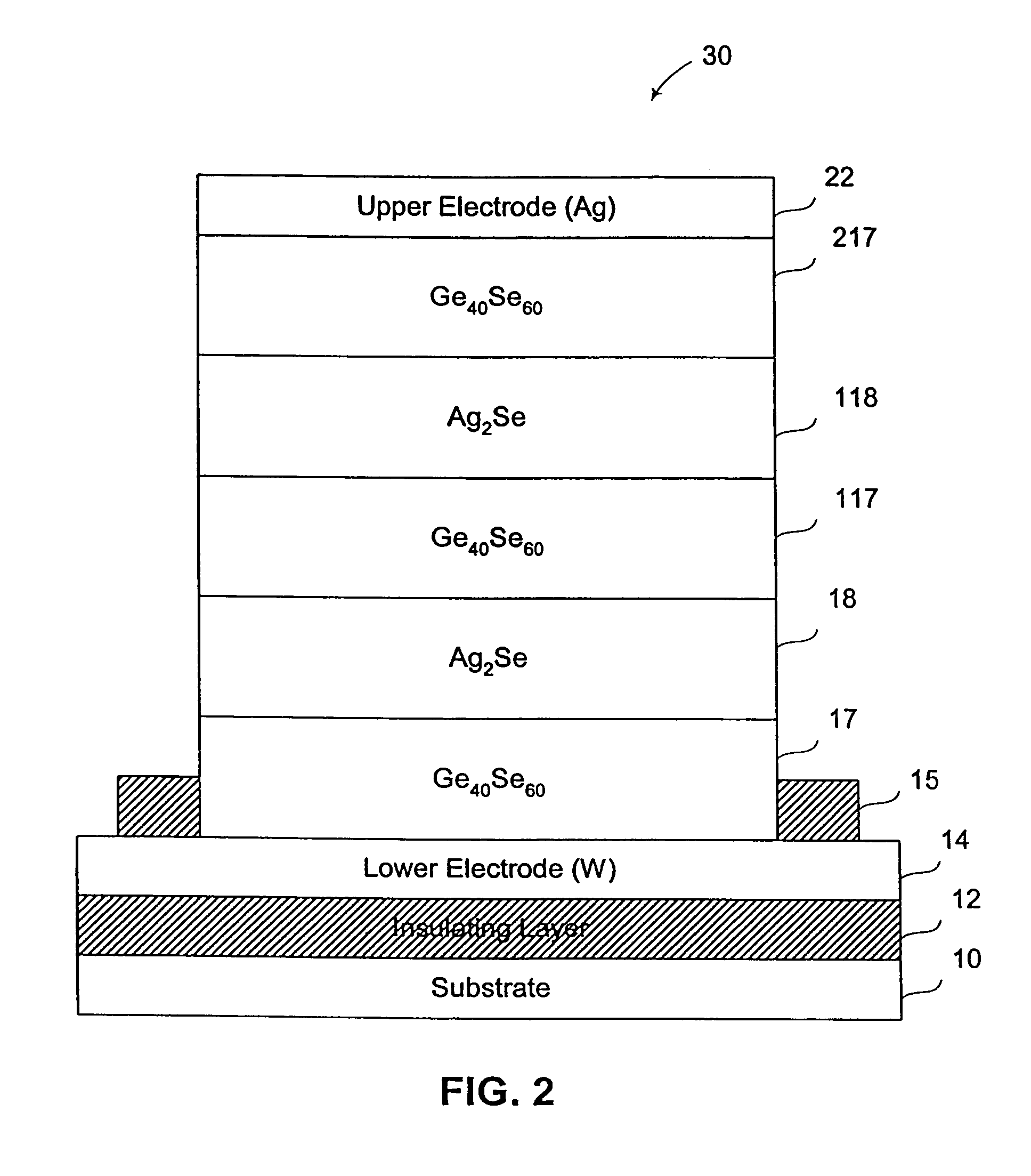
second embodiment
[0044]In accordance with the second embodiment, the stack includes at least two metal containing layers and at least three chalcogenide glass layers. However, it is to be understood that the stack may include numerous alternating layers of chalcogenide glass and silver-selenide, so long as the alternating layers start with a first chalcogenide glass layer and end with a last chalcogenide glass layer, with the first chalcogenide glass layer contacting a first electrode and the last chalcogenide glass layer contacting a second electrode. The thickness and ratios of the alternating layers of silver-selenide and chalcogenide glass are the same as described above, in that the silver-selenide layers are preferably thicker than connecting chalcogenide glass layers, in a ratio of between about 5:1 and about 1:1 silver-selenide layer to connected chalcogenide glass layer, and more preferably between about 3.3:1 and 2:1 silver-selenide layer to connected chalcogenide glass layer.
[0045]In a va...
PUM
 Abstract
Description
Claims
Application Information