
Vivaldi antenna

a vivaldi antenna and antenna technology, applied in the field of antennas, can solve the problems of poor performance of conventional exponential flare vivaldi antennas, poor physical implementation performance of conventional antennas, and inability to operate so straightforwardly, so as to achieve the effect of eliminating discontinuities

Inactive Publication Date: 2006-08-08
ROKE MANOR RES LTD
View PDF6 Cites 43 Cited by
  • Summary
  • Abstract
  • Description
  • Claims
  • Application Information

AI Technical Summary

Benefits of technology

[0027]Advantageously, the or each of said nodes may be blended to eliminate discontinuities.

Problems solved by technology

The performance of physical implementations of conventional antennas is degraded by a number of complicating factors.
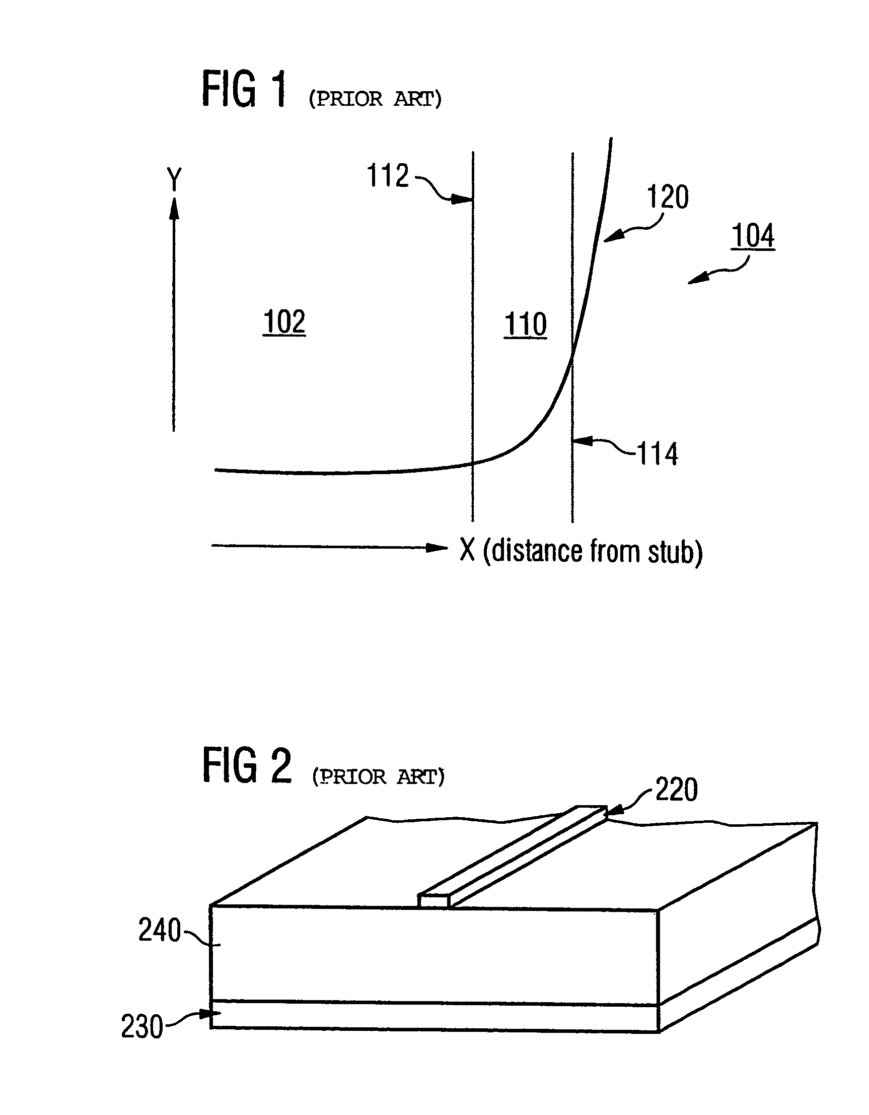
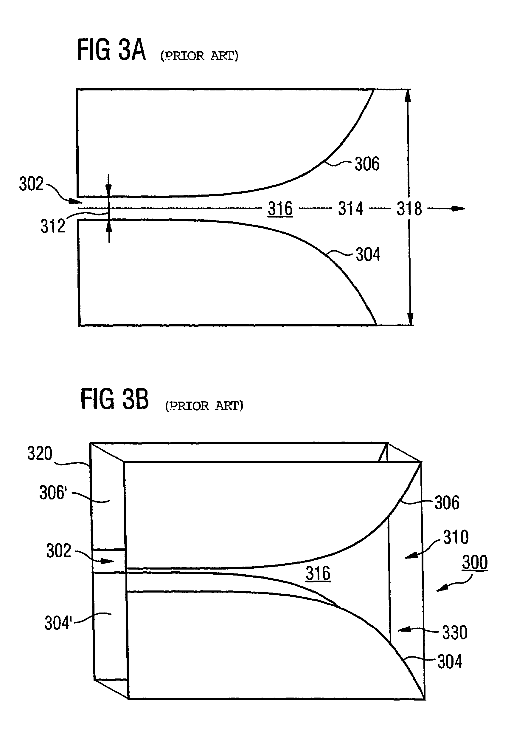
It has been established experimentally that the conventional exponential flare shaped Vivaldi antenna has poor performance over ultra-wide bandwidths.
In the real world, antennas do not function so straightforwardly.
As the slot becomes wider the gradient of the exponential curve increases and becomes too steep to radiate effectively.

Method used


Image

  • Vivaldi antenna
  • Vivaldi antenna
  • Vivaldi antenna

Examples


first embodiment

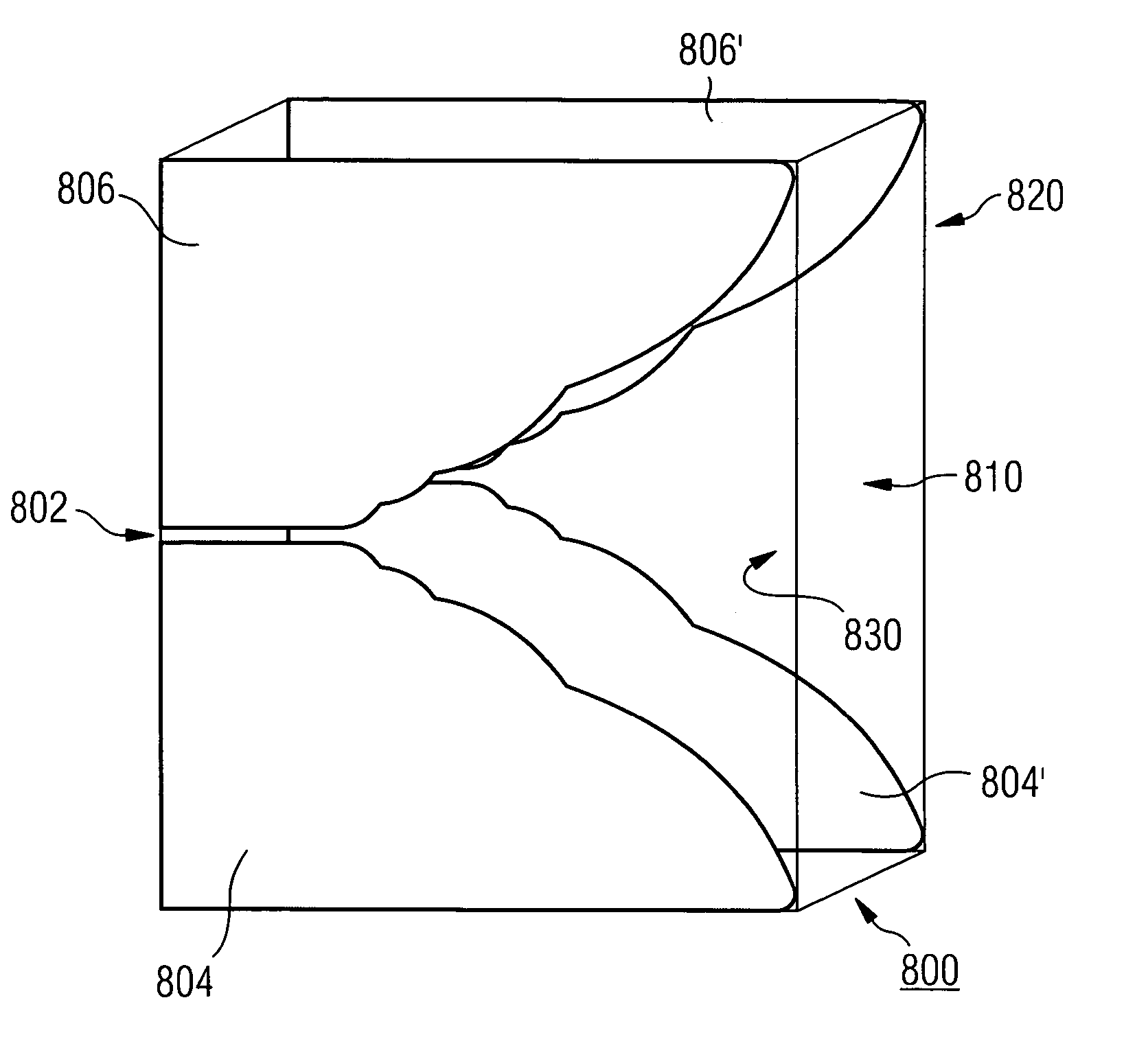
[0068]In this first embodiment of the present invention, the hybrid fractalized curve 620 constructed from four exponential curve sections is implemented on the inner edge of the wing regions 804,806, 804′,806′.

[0069]The antenna arrangement shown in FIG. 9 is also constructed from a single sheet 910 of double sided copper clad dielectric substrate. On this occasion the antenna is fed by a twinline 902.

second embodiment

[0070]FIG. 9 shows the present invention in which the hybrid fractalized curve 620 is applied to the inner edges 914 of the conductive wing regions 904,906 in an unbalanced antipodal configuration 900.

[0071]It is noted that the trailing edges 912 of the conductive wing regions are also formed in accordance with a hybrid fractalized curve. Furthermore the series of curve sections making up the fractalized trailing edge 912 may be blended as described in FIGS. 7A to 7E. The use of hybrid curves on the trailing edge 912 can help reduce low frequency return loss.

[0072]The balanced antipodal Vivaldi antenna shown in FIG. 10 is constructed from two sheets of double sided copper clad dielectric substrate 1030,1050 sandwiched together and is fed from a balanced twinline 1002.

third embodiment

[0073]FIG. 10 shows the present invention in which the hybrid fractalized curve 620 is applied to the inner edges 1014 of the conductive wing regions 1004,1006 in a balanced antipodal configuration 1000.

[0074]Again the trailing edges 1012 of the conductive wing regions 1004,1006 are also formed in accordance with a hybrid fractalized curve.

[0075]As will be understood antennas in accordance with the present invention may constructed from a conductor clad dielectric microwave substrate material just as conventional Vivaldi antennas are. The type of construction depends upon the type of feed to the antenna which in turn depends upon the particular class of antenna implemented.

[0076]The foregoing discussion considered the arrangement of a single antenna. It is however well known in the art to form arrays from a plurality of similar antennas. Furthermore it is known to provide antennas with identical endfire directions but rotated at an angle relative to one another about the endfire axi...


PUM


Abstract

A directional, wideband, planar antenna arrangement is a class of Vivaldi aerial constructed as a plurality of conductive layers disposed on at least one substrate layer. The conductive layers are arranged to form a flared notch, which widens from a closed end to an open end, and is arranged to conform to a hybrid curve. The hybrid curve comprises a plurality of self-similar curve sections, and, as the flare widens, each successive curve section is scaled up by a scaling factor and joined at its wider end with a neighboring curve section. The hybrid flared notch can also be implemented in antipodal and balanced antipodal Vivaldi aerials.

Description

BACKGROUND OF THE INVENTION[0001]The present invention relates to improvements in antennas. In particular the present invention relates to broadband antenna of the Vivaldi, notch or tapered slot antenna family.[0002]The Vivaldi antenna element was proposed by Gibson in 1979, (P. J. Gibson, The Vivaldi Aerial, in Proc. 9th European Microwave Conference, UK, June 1979, pp. 101–105). The original Vivaldi antennas were tapered notch antennas having notches which open in an exponential flare shape. They were constructed by conventional microwave lithographic thin film techniques on substrates having a high dielectric constant, for example, alumina. Gibson's work has subsequently developed to include high gain Vivaldi antennas constructed on ceramic substrates other than alumina which have high dielectric constants and on substrates having low dielectric constant, for example, plastics. Copper-clad plastics (cuclad), for example PTFE, RT / duroid (having a variety of values, typically r=2.2...

Claims


Application Information

Patent Timeline
Patent Type & Authority Patents(United States)
IPC IPC(8): H01Q13/10H01Q13/08
CPCH01Q13/085
Inventor FISHER, JAMES JOSEPH
Owner ROKE MANOR RES LTD
Learn More