Equipment of a weaving machine, method for the modification of a weaving machine equipment, and weaving process making use of a weaving machine having such equipment

a technology of weaving machine and equipment, which is applied in the field of weaving machine equipment, can solve the problems of time-consuming and laborious modification of the equipment of the weaving machine, and achieve the effect of improving the quality of weaving

Inactive Publication Date: 2006-08-15
N V MICHEL VAN DE WIELE
View PDF22 Cites 6 Cited by
  • Summary
  • Abstract
  • Description
  • Claims
  • Application Information

AI Technical Summary

Problems solved by technology

Such a modification of the equipment of a weaving machine is particularly time-consuming and laborious.

Method used


Image

  • Equipment of a weaving machine, method for the modification of a weaving machine equipment, and weaving process making use of a weaving machine having such equipment
  • Equipment of a weaving machine, method for the modification of a weaving machine equipment, and weaving process making use of a weaving machine having such equipment

Examples


Embodiment Construction

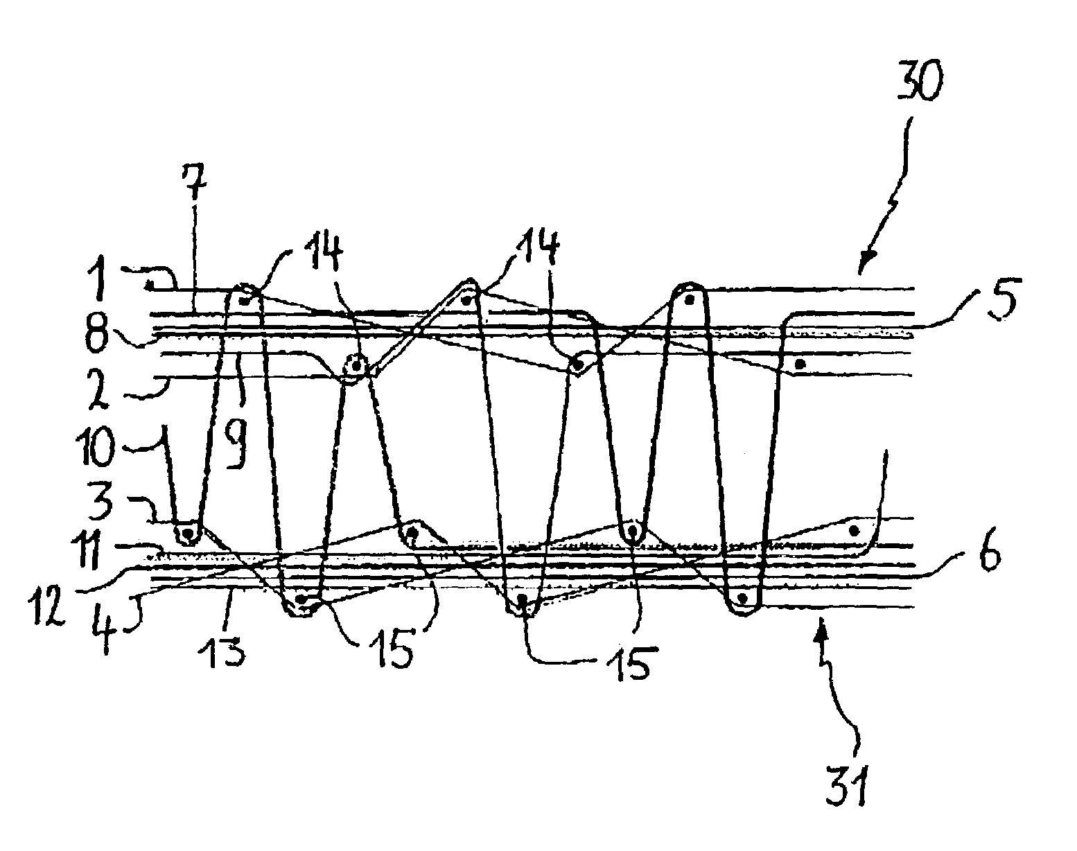
[0044]The face-to-face pile fabric represented in the figures consists of an upper and a lower backing fabric. Both backing fabrics consist of binding warp yarns, tension warp yarns and weft yarns. Pile forming pile warp yarns are interlaced in the upper and lower backing fabric alternately over a weft yarn, while dead pile warp yarns are interlaced in the upper or lower backing fabric.

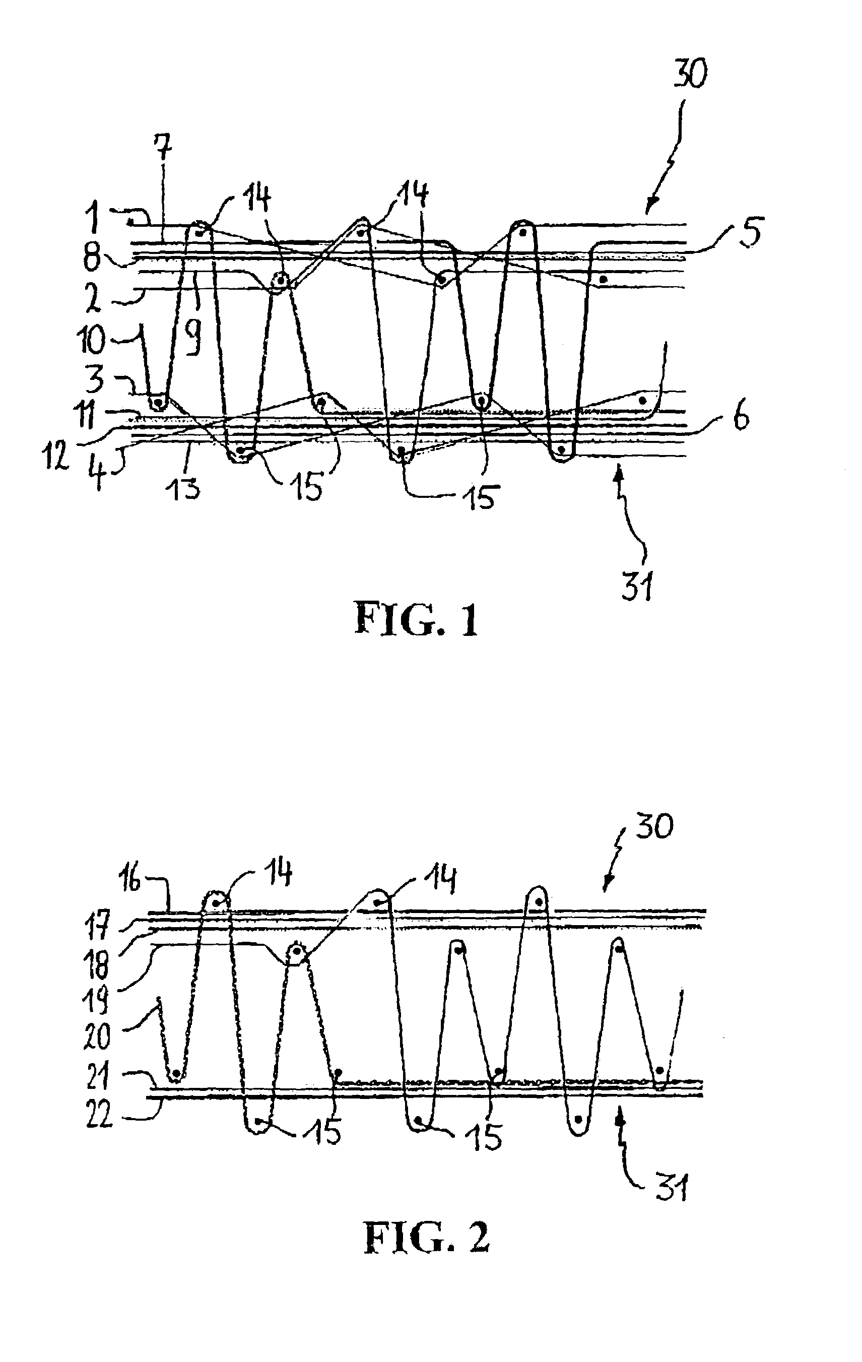
[0045]The face-to-face fabric represented in the figures consists of an upper (30) and a lower backing fabric (31) which are woven according to a well-determined, commonly known backing weave. The upper backing fabric is woven from weft yarns (14), binding warp yarns (1),(2) and tension warp yarns (5). The lower backing fabric (31) is woven from weft yarns (15), binding warp yarns (3),(4) and tension warp yarns (6).

[0046]In order to obtain these backing fabrics, the weaving machine is provided with a series of backing warp yarn systems, which comprise the binding warp yarns (1–4) and the tension warp ...


PUM


Abstract

An equipment of a weaving machine in which pile warp yarns (7–13), (16–22) extend through the space between the reed dents and are distributed between a number of pile warp yarn systems and provided on the weaving machine to weave a pile fabric. A group of pile warp yarns (7–22) extend through each space between the reed dents and comprise pile warp yarns of at least two pile warp yarn systems (7–13), (16–22). Because of this it is possible to weave pile fabrics having higher pile densities at a certain reed setting. It is an easy and quick method to modify the equipment of a weaving machine, maintaining the reed setting and the pile warp yarns of each space between the reed dents being distributed between at least two pile warp yarn systems. Furthermore, a weaving process is provided in which, per space between the reed dents the pile warp yarns (7–13), (16–22) of at least two pile warp yarn systems are supplied and a pile fabric woven in that manner. The number of complete backing warp yarn systems is smaller than or equal to the number of pile warp yarn systems.

Description

[0001]This application claims the benefit of Belgian Application No. 2002 / 0019 filed Jan. 11, 2002.BACKGROUND OF THE INVENTION[0002]This invention relates to an equipment of a weaving machine, in which pile warp yarns extend through the space between reed dents and, distributed between a number of pile warp yarn systems, are provided on the weaving machine in order to weave a pile fabric.[0003]This invention relates to both the equipment of a face-to-face weaving machine and to a single fabric weaving machine, such as, for instance, a rod weaving machine or a loop pile weaving machine.[0004]More particularly, this invention relates to the equipment of a face-to-face jacquard weaving machine, and among others also to rod and loop pile weaving machine having a jacquard machine.[0005]This invention likewise relates to a method for the modification of the equipment of a weaving machine on which pile warp yarns extend through the space between reed dents and, divided between a number of ...

Claims


Application Information

Patent Timeline
Patent Type & Authority Patents(United States)
IPC IPC(8): D03D39/00D03D39/16D03D27/06D03D27/10
CPCD03D27/06D03D39/16D03D39/00D03D27/10
Inventor DEBAES, JOHNY
Owner N V MICHEL VAN DE WIELE
Why Eureka
Try Eureka