

Card connector
a card and connector technology, applied in the direction of coupling device connection, massage belt, instruments, etc., can solve the problems of unsuitable card heat dissipation, operational malfunction, and card will be elevated,
- Summary
- Abstract
- Description
- Claims
- Application Information
AI Technical Summary
Benefits of technology
Problems solved by technology
Method used
Image

Examples
second embodiment
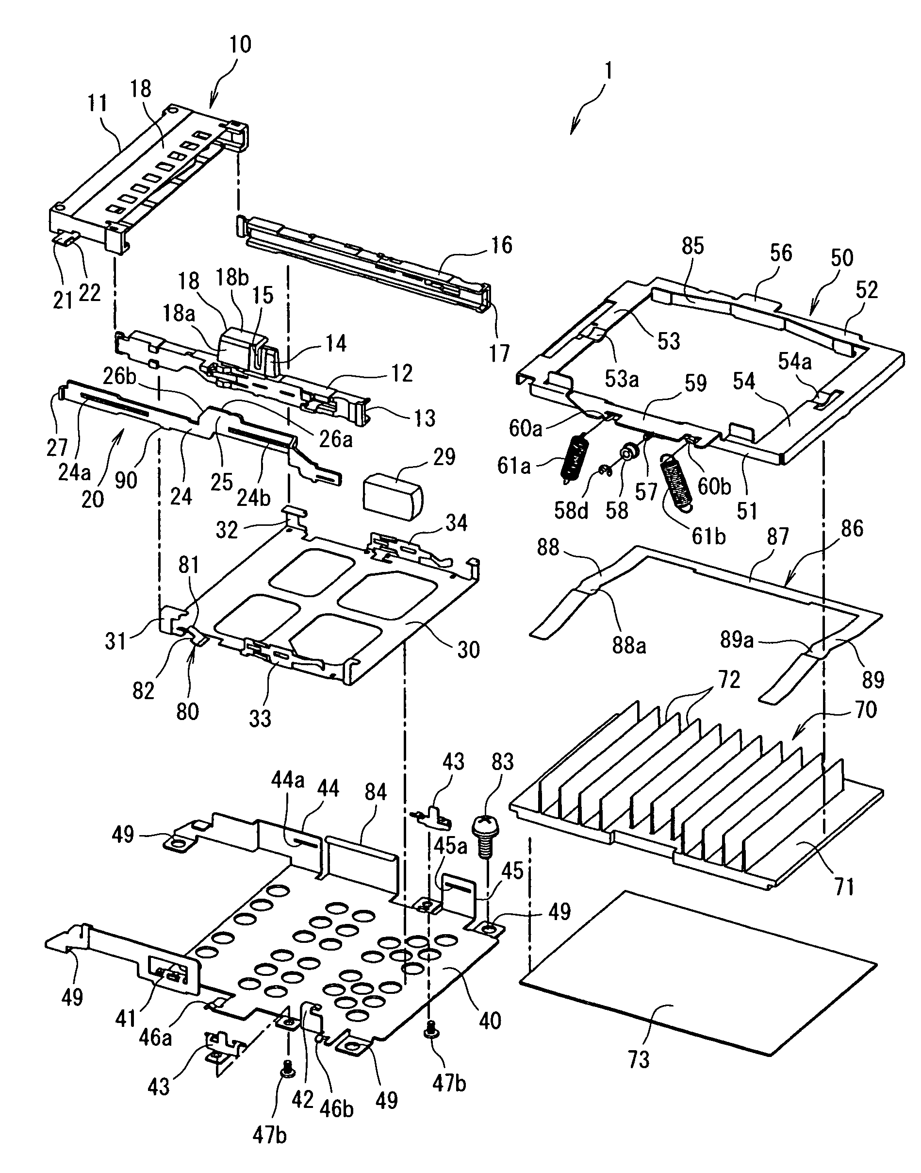
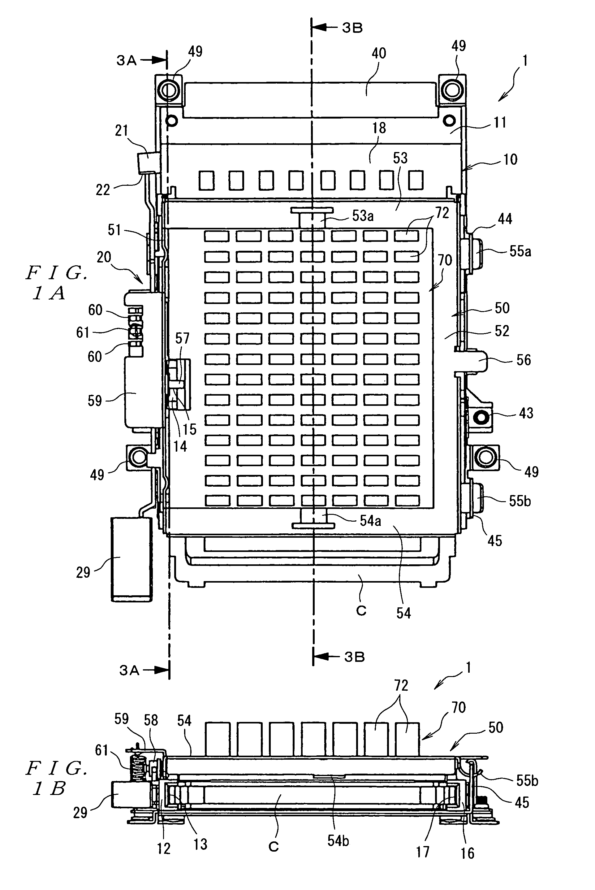
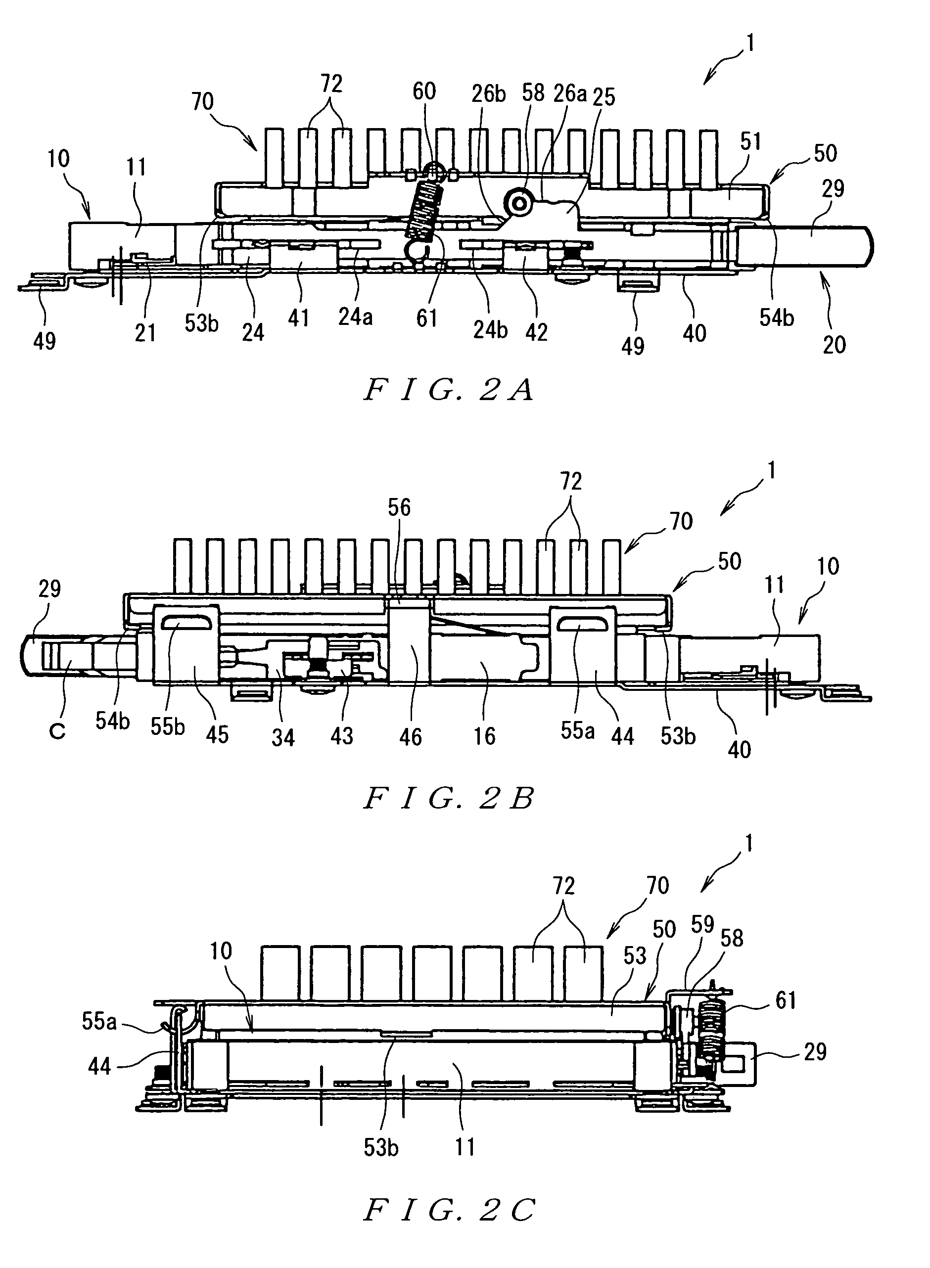
[0057]Next, the card connector of the present invention will be described with reference to FIGS. 7, 8, 9A and 9B, 10A and 10B, and 11A and 11B. In FIGS. 7, 8, 9A and 9B, 10A and 10B, and 11A and 11B, the card connector 1 comprises a connector part 10 into which a card C is inserted, and an ejection mechanism 20 which ejects the card C from the connector part 10.
[0058]The connector part 10 comprises a header 11 into which the card C is inserted and which has a plurality of contacts (not shown in the figures) that are contacted by the contacts (not shown in the figures) of the card C, and a pair of guide arms 12 and 16 which extend rearward (downward in FIG. 9A) from either side portion of the header 11 in the direction of width (left-right direction in FIG. 9A). The respective guide arms 12 and 16 are press-fitted to either side portion of the header 11 in the direction of width in the front end portions of these guide arms. Furthermore, a ground plate 18 is disposed on the upper su...
third embodiment
[0082]Next, the card connector of the present invention will be described with reference to FIGS. 12 through 14, 15A to 15E, and 16A to 16E. In FIGS. 12 through 14, 15A to 15E, and 16A to 16E, the card connector 1 comprises a connector part 10 into which a card C is inserted, and an ejection mechanism 20 which ejects the card C from the connector part 10.
[0083]Between these parts, the connector part 10 comprises a header 11 into which the card C is inserted and which has a plurality of contacts (not shown in the figures) that are contacted by the contacts (not shown in the figures) of the card C, and a pair of guide arms 12 and 16 which extend rearward (downward in FIG. 12) from either side portion of the header 11 in the direction of width (left-right direction in FIG. 12). The respective guide arms 12 and 16 are press-fitted to either side portion of the header 11 in the direction of width in the front end portions of these guide arms. Furthermore, a ground plate 18 is disposed on...
PUM
 Abstract
Description
Claims
Application Information