LED connector

a technology of led connectors and connectors, applied in the direction of electrical equipment, contact members penetrating/cutting insulation/cable strands, coupling device connections, etc., can solve the problems of not providing led arrays, inability to array leds in necessary lateral proximity, and conventional connectors are quite expensive compared to achieve the effect of enhancing the orientation correction featur

Inactive Publication Date: 2006-08-15
SHANGHAI JIATANG ELECTRONICS
View PDF2 Cites 15 Cited by
  • Summary
  • Abstract
  • Description
  • Claims
  • Application Information

AI Technical Summary

Benefits of technology

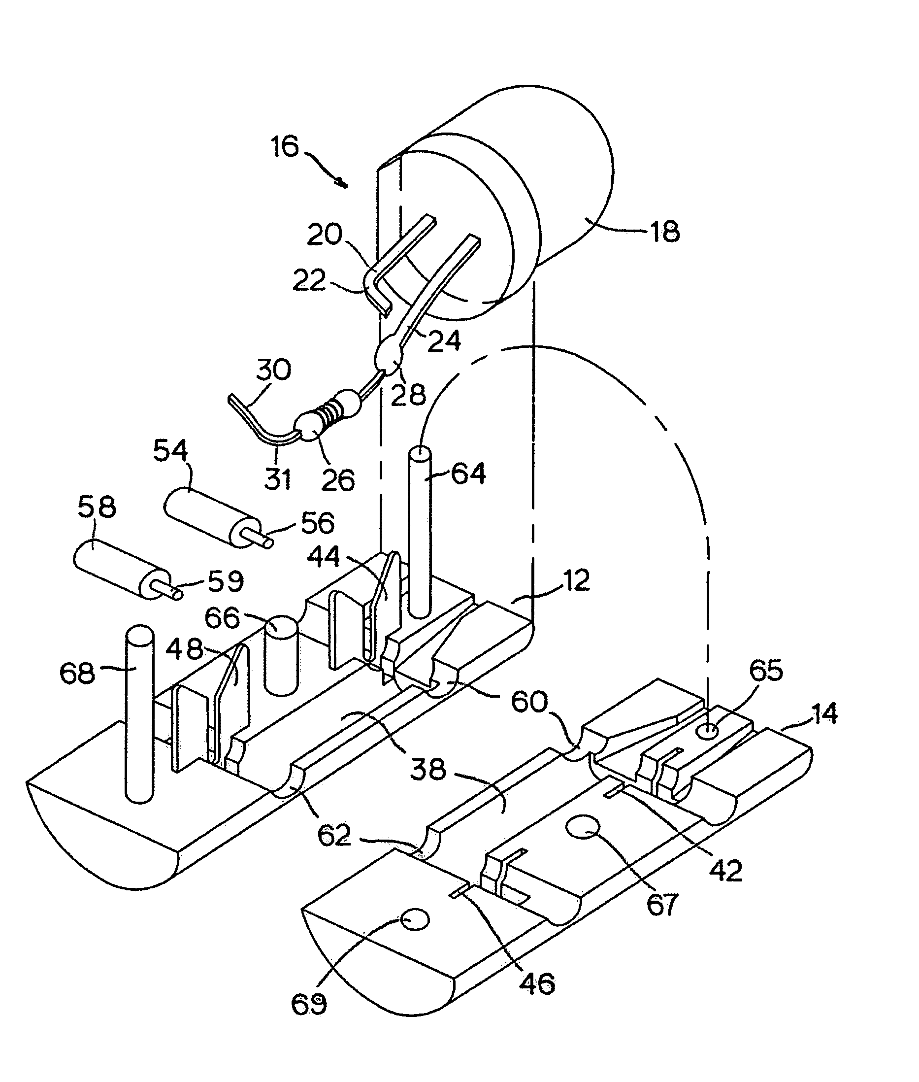
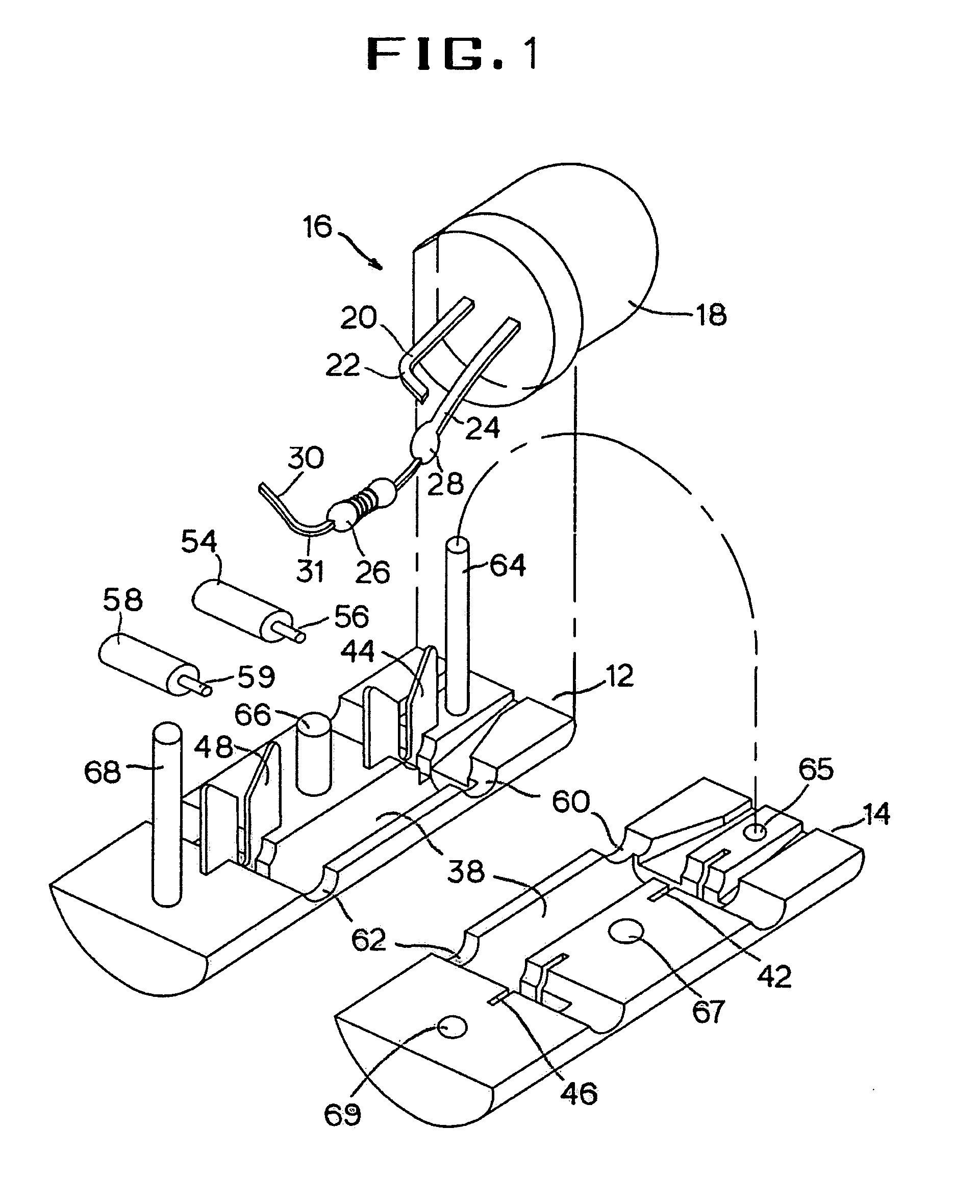
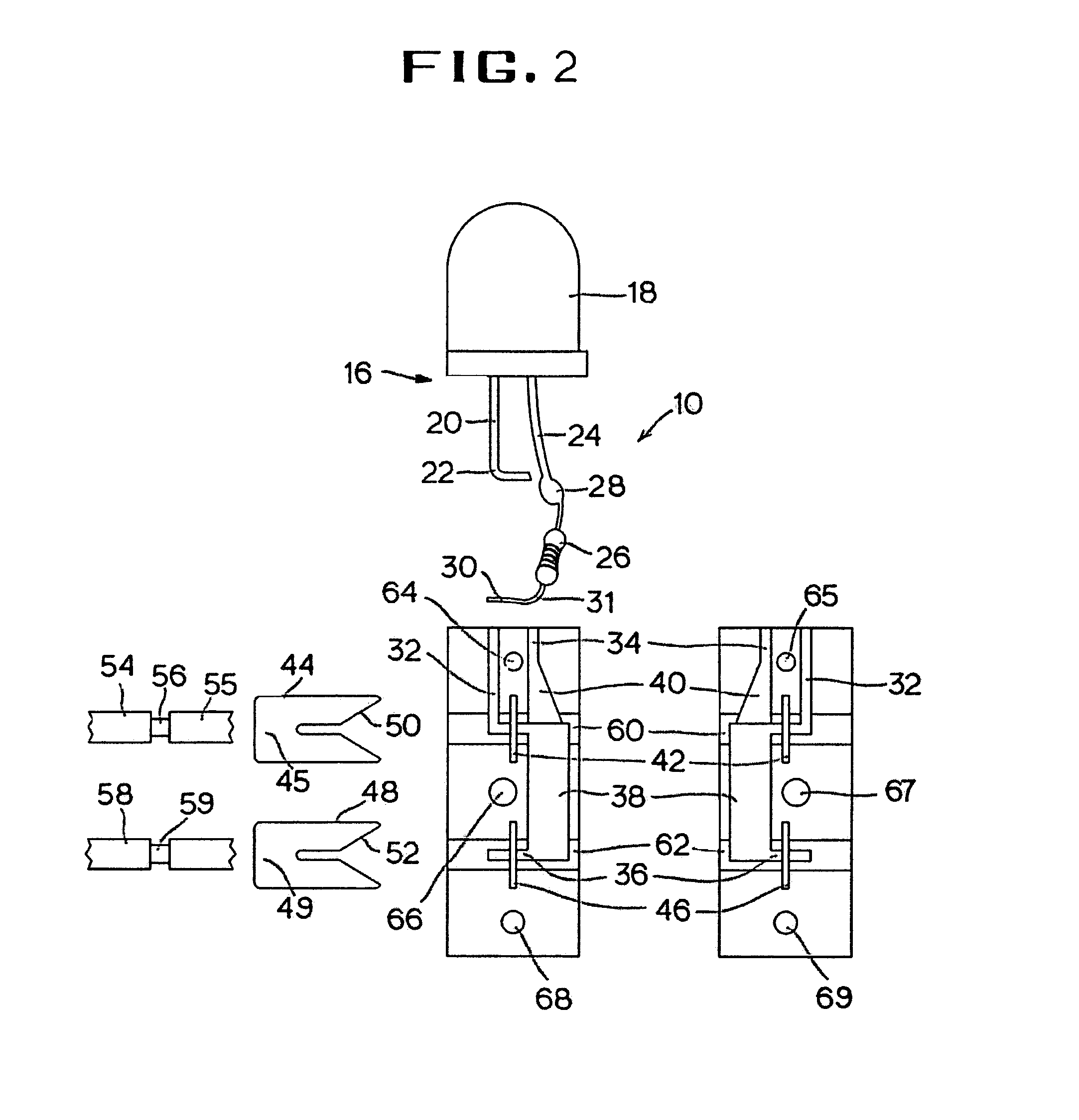
[0020]A middle post similarly protrudes from the connector half, but is thicker than the top post and serves as a middle anchor for reinforced fastening. Therefore, the protruding height of the middle post may be lower than the top post and is adapted for insertion into the corresponding pinhole on the second connector half. The post is not necessarily opened throughout its thickness. Additionally, the middle post is positioned off center from the longitudinal location of the top post in order to prevent the two connector halves from being engaged in a wrong orientation wherein the middle post is led to impede other flat regions of the second connector half than its pinhole.
[0021]A bottom post has a third thickness different from those of the top and middle posts to further enhance the orientation correction feature. This post is positioned in the longitudinal center and will be engaged with the corresponding hole on the second connector half in assembly. The distal end of the bottom post may extend beyond the thickness of the connector half that penetrates the opposite opening of the hole. Any such overextending portion may be used later as a releasing push button as well.

Problems solved by technology

This prior art connector may be suitable for a single dot of light, however it does not provide for a LED array wherein numerous dots of LEDs are packed tightly into plain layout areas.
A problem lies within conventional LED connectors when they are applied to electric signage.
They are unable to array the LEDs in necessary lateral proximity because conventional LED connectors' inherently large latitudinal space keeps the LEDs from adjoining each other.
Additionally, conventional connectors are quite expensive compared to the cost of LEDs themselves, which have been steadily decreasing in price with the improvement of manufacturing.

Method used


Image

  • LED connector
  • LED connector
  • LED connector

Examples


Embodiment Construction

[0027]Referring to FIG. 1, the LED connector 10 mainly comprises a first half section 12 and a second half section 14 forming together a round column having flat top and bottom ends and its cross sectional area no larger than that of a lamp 16. The connector halves 12 and 14 have generally flat opposing surfaces, which come into full contact with each other when they are assembled.

[0028]The lamp 16 has an LED 18 in the shape of a solid dome with an annular flat bottom and a pair of leads extending outwardly from the flat bottom. A first lead 20 is prepared for electrical connection with a bend22 formed at a predetermined distance near its distal end. A second lead 24 may have a resister 26 soldered at a point 28 to its distal end to supply a regulated electric current to the LED 18. The second lead 24 is prepared for electrical connection via a bend 30 formed at a free lead 31 of the resister 26, which will be scrutinized in further detail below.

[0029]To retain the lead 20, on the i...


PUM


Abstract

The present invention is a LED connector principally comprised of two compatible halves with flat opposing surfaces, which form a complete cylinder when placed together. Its cross sectional area is no larger than that of the LED lamp.
The solid-dome shaped LED component has an annular flat bottom that holds an outwardly extended pair of leads. Two parallel L-shaped recesses extend longitudinally over the connector half's flat surface. A large groove aligned with longer recess is included to accommodate the resister's solder. A pair of strategically spaced slots are formed longitudinally in the connector half's central region. The top slot holds a first conductive terminal member, and the bottom slot holds a second terminal member with their bases, respectively.
The opposing connector's flat surface bears the same layout of recesses, slots and grooves. When the connector's halves are adjoined, electrical connections between the LED lamp and wires can be firmly secured and insulated. This interaction is conducted within the radius of the LED component, and is easily reversed by simple rewiring via the unique fastening means. Fastening means include three perpendicularly protruding posts with corresponding pinholes within the connector. Each of said posts and pinholes are individually sized and located in corresponding orientations of the first and second connector halves.

Description

BACKGROUND OF THE INVENTION[0001]A. Field of the Invention[0002]The present invention relates to an electric component, and more particularly to a miniature pin-mount connector for light emitting diodes used in electric signage or other displays.[0003]B. Description of the Prior Art[0004]Small light bulb arrays with supporting sockets are previously identified in the art, as suggested by U.S. Pat. No. 2,265,360 to F. M. Dessart and U.S. Pat. No. 2,506,620 to E. V. Sundt. Their primary uses are for Christmas ornaments that connect multiple small bulbs in parallel to a pair of electric wires by their respective terminal structures or sockets. The wires are enclosed either permanently in the sockets' manufacture, yielding a molded structure, or semi-permanent structure. Both methods generally require heat energy in setting the sockets to hold the electric wires in place.[0005]These and other prior art sockets are designed for holding separate bulbs at a distance from each other. The in...

Claims


Application Information

Patent Timeline
Patent Type & Authority Patents(United States)
IPC IPC(8): H01R11/20
CPCH01R33/05H01R4/2433
Inventor WANG, XIAO-PING
Owner SHANGHAI JIATANG ELECTRONICS
Why Eureka
Try Eureka