Activity surfaces

a technology for activity surfaces and surfaces, applied in the field of activity surfaces, can solve the problems of wear and tear on the activity surface contained within the venue, affecting the upkeep affecting the operation of the activity surface, so as to achieve easy replacement, minimise the amount of wear, and easy control

Inactive Publication Date: 2006-08-15
ASCOT RACECOURSE
View PDF45 Cites 17 Cited by
  • Summary
  • Abstract
  • Description
  • Claims
  • Application Information

AI Technical Summary

Benefits of technology

[0021]The present invention in one of its broadest aspects resides in the appreciation that there is a viable alternative to the underpass solution. In particular, the present inventors have appreciated that the solution is to use one or more movable turf trays to temporarily reconfigure the crossing for use by the horses rather than the road vehicles. This option is far cheaper than building an underpass.

Problems solved by technology

Whilst the design of such multi-purpose venues primarily focuses on the needs of spectators, the wear and tear on the activity surface contained within the venue can be a ground-keeper's nightmare.
Both single and multi-purpose activity surfaces are subject to wear and tear through use and exposure to the elements.
Exposure to the elements further complicates the upkeep of an activity surface and, despite the best endeavours of all concerned, some areas can never be returned to a satisfactory state.
Attempts to solve this problem by enclosing the activity surface are not always successful, especially where the activity surface is turfed as the resulting environment may be inhospitable to the turf surface.
For young horses this has however, always been a problem which causes adverse reaction in the horse's behaviour.
Recently, some young horses have actually broken their hoofs on the harder road crossing section of the racetrack.
The major difficulty with this proposal is that of cost.
Building such a road tunnel or underpass is extremely expensive and also requires local planning permission to be obtained.
However, the present inventors have realised that there are a number of disadvantages with existing systems and methods which, for example, make them unsuitable for solving the problems associated with racetrack crossings.
However, the difficulty with these types of turf moving systems is that the units are designed to be replaceable infrequently, namely that they are semi-permanent.
Accordingly, these types of systems are not designed to be readily reconfigurable.
Furthermore, the units' assembly can take a long time as the units have to be physically connected together and then the upper turfed surface constructed by the addition of topsoil and turf.
However, in practice, as the pliable edging has different deformation characteristics to natural turf and soil, the pliable edging can interfere with the performance of the sports surface.
However, the pliable edging used does not have this variation in its deformation characteristics such that in some weather conditions, the performance of the sports surface at the edging is too different to that of the surrounding turf to be acceptable.
The types of turf trays described in WO-A-95 / 33890 are not suitable for use in reconfigurably closing a gap in a pathway such as a racetrack or, in fact, for reconfigurably closing a gap between any two fixed opposing edges of an activity surface.
This is because in order to move a movable tray into its final position within a gap, an excessive amount of rubbing is caused between the edges of the tray and those of the fixed activity surface which leads to an unacceptable amount of wear at the join between the activity surface and that of the tray surface.
More specifically, excessive wear can lead to dangerous gaps in the activity surface appearing.
Furthermore, the prior art turf tray systems are not designed to be moved frequently and as such there is no appreciation of the problems of maintaining a turf edge which has to be engaged and disengaged from the edges of the activity surface quickly and repetitively without substantial deterioration.
This type of system is at least semi-permanent and is not suitable for the frequent replacement of a section of the original activity surface.
In addition, the resulting arrangement is not able to be removed and replaced relatively quickly, and the construction of the arrangement on top of the original activity surface is likely to damage the latter, which is unacceptable.
The quality of the activity surface is not suitable for use in relation to turfed activity surfaces or where a seamless join between the sections is required.
Furthermore, as with GB 319 472 this system has the disadvantage of not being readily reconfigurable, and the movement of the sections across the horse racetrack may result in damage to same, which is unsatisfactory.
However, the system is not designed to be used for closing a gap as the edge profile of each element would degrade unacceptably if used in this manner.
However, an activity surface formed using such turf units is not reconfigurable without damage to the activity surface itself and is also unsuitable for closing a gap in an activity surface.
Accordingly, as mentioned before the existing turf tray moving systems are not suitable for closing a fixed gap in an activity surface and so could not be used as part of a reconfigurable racetrack crossing.

Method used


Image

  • Activity surfaces
  • Activity surfaces
  • Activity surfaces

Examples


first embodiment

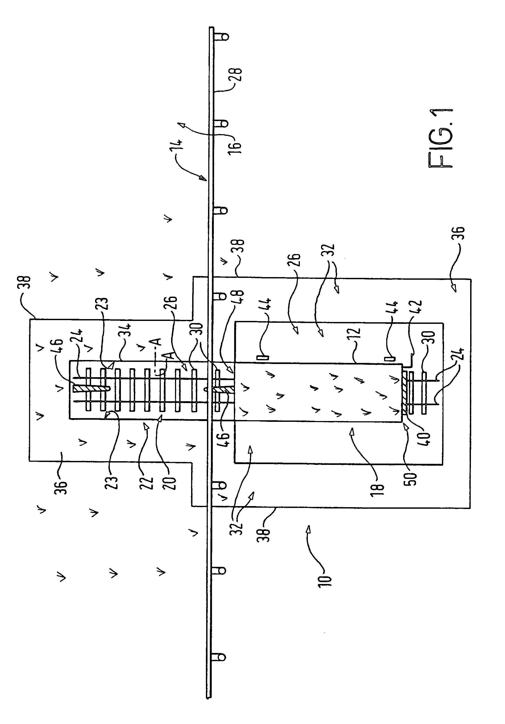
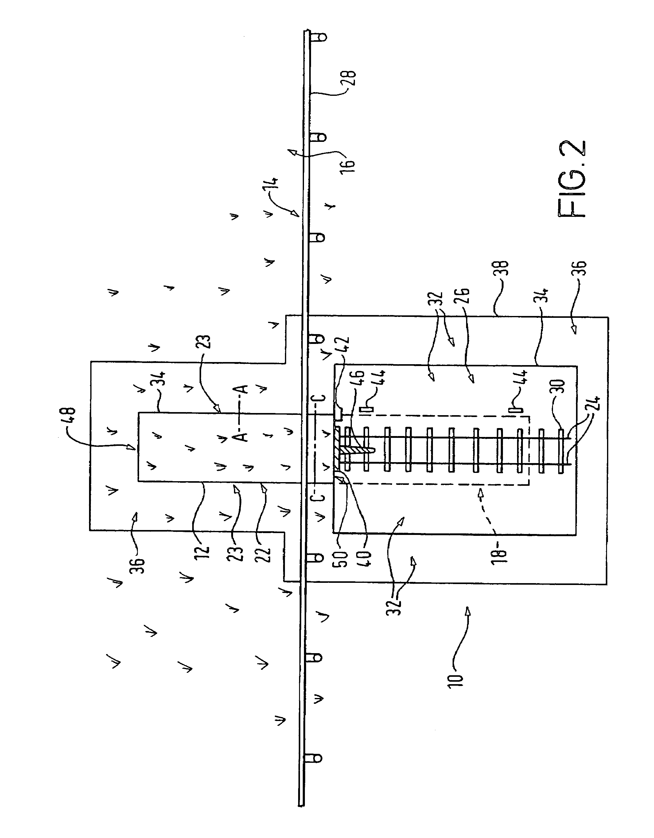
[0079]Referring now to FIGS. 1 and 2, a turf tray moving system 10 of the present invention comprises a movable turf tray 12 which is arranged to be movable, substantially at right angles to an edge 14 of a racetrack 16, between two locations each representing a different racetrack mode. In a non-race (open) mode, the turf tray 12, at a first location 18 (FIG. 1), is spaced apart from a gap 20 in the turfed racetrack 16. In a race (closed) mode, the turf tray 12 at the second location 22 (FIG. 2), is adjoined to edges 23 of the racetrack 12 which define the gap 20 and accordingly fills the gap 20. In this embodiment, the turf tray 12 is provided on a wheeled platform (see FIGS. 5a to 5d and 6a to 6d) and is movable between the first and second locations 18, 22 by way of guide rails 24.

[0080]The turf tray moving system 10 is provided within an excavated pit 26 which partially overlaps a portion of the racetrack 12 (the edge 14 of the racetrack 12 being defined by a running rail 28). ...

third embodiment

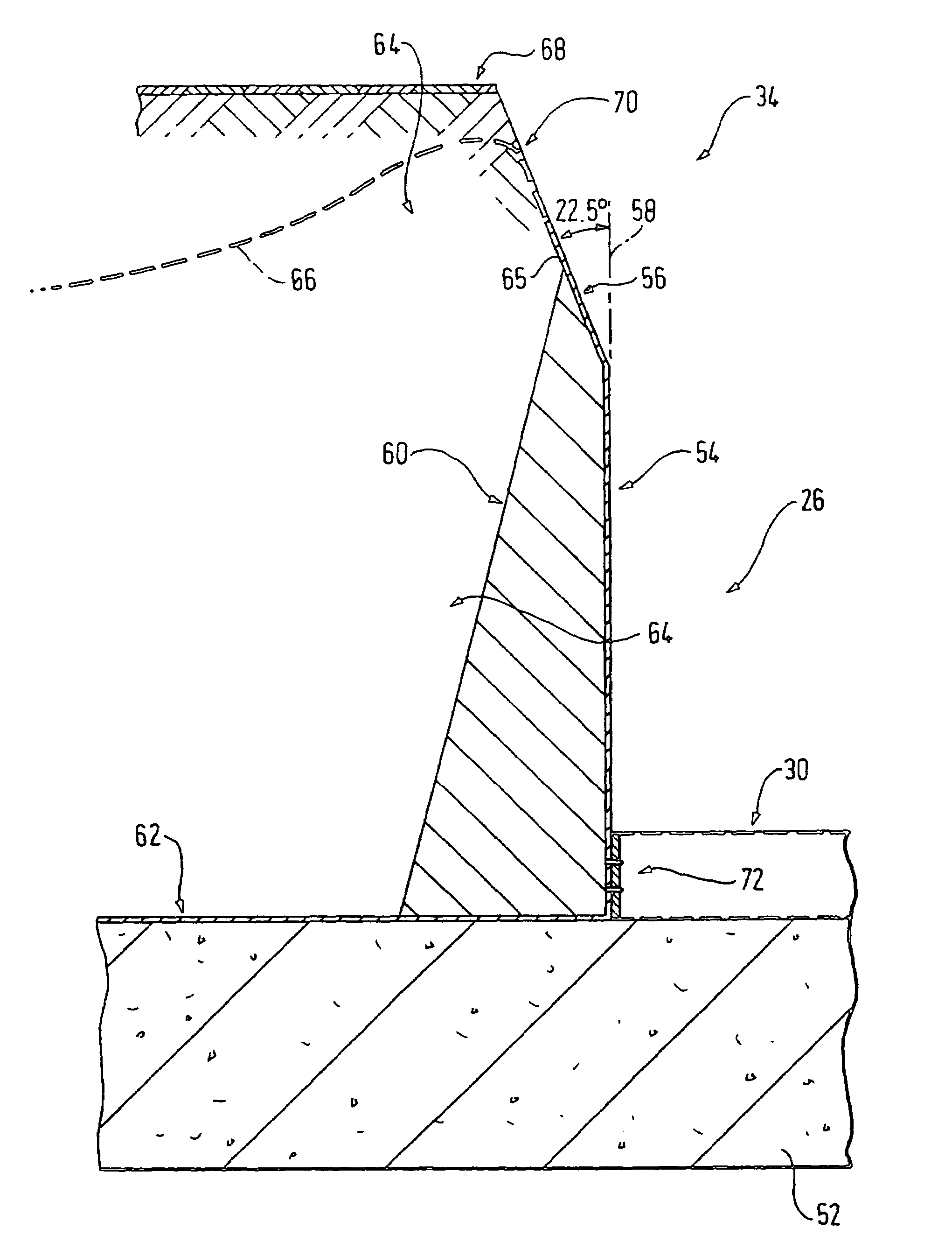
[0122]In contrast to the previous two embodiments, the third embodiment does not employ overlapping angled turfed edges. The first and second edges 218, 222 of the racetrack 206, the leading and trailing edges 216, 220 of pallet no. 1200 and the elongate side edges 228 of pallet no. 2202 all comprise substantially vertical complimentary engagement surfaces. In this case, the flexible edge reinforcement material extends vertically from the ends of the turf tray upstanding side walls to provide support for the flexible edges 216, 220, 228 of each turf tray 200, 202. The flexible edge reinforcement material is positioned so as to extend slightly over the vertical line of each upstanding turf tray side wall. This enables a good contact to be made between the sides of each turf tray 200, 202 and the complimentary flexible side walls 220, 228 of the other turf tray 200, 202 or racetrack edge 218, 222, when the two are brought together.

[0123]In the previous embodiment, is little or no rela...


PUM


Abstract

An apparatus for an a method of closing a fixed gap in an activity surface such as a turfed race-track is described. The apparatus comprises a movable turf tray having an upper surface with the same characteristics as the activity surface and means for guiding the tray into the gap so as to wedge the tray releasably in the gap and thereby to provide a substantially continuous activity surface. The apparatus can be used to provide a reconfigurable racetrack crossing with the permanent road gap in the racetrack being closeable by means of the movable turf tray. Overlapping edges of the turf tray provide a weight wedging action which provides reliable pressure joins. This also has application for creating reconfigurable turfed activity surfaces such as are used in sports stadia and the like.

Description

[0001]The present invention concerns improvements relating to activity surfaces such as racetracks and more particularly, though not exclusively, to a novel method and apparatus for reconfiguring a crossing at a turfed racetrack. The present invention also has utility in replacing worn surfaces of turfed and non-turfed sports surfaces such as pitches and racetracks. Furthermore the present invention also concerns improvements relating to the joining of sections of turfed surfaces together or sections of non-turfed surfaces together.BACKGROUND[0002]As the populations of our cities and towns increase, so does the need to provide multi-functional venues or stadia where we can watch, play or participate in a variety of sports or other activities. Increasingly these days a sports stadium may double as a football pitch, hockey field and athletics track, whereas the local racecourse also caters for both dog racing and horse racing. In our larger cities, international-standard stadia are us...

Claims


Application Information

Patent Timeline
Patent Type & Authority Patents(United States)
IPC IPC(8): E01C13/00A63C19/00A63B71/00A63C19/02A63K1/00E01C13/08
CPCA63C19/00A63C19/02E01C13/083A63K1/00E01C2013/006
Inventor EVERETT, ROBERTMORLEY, STEPHENWHITWORTH, ANDREWMORTON, PAUL
Owner ASCOT RACECOURSE
Why Eureka
Try Eureka