System and method for using multiple medical monitors

a medical monitor and monitor technology, applied in the field of medical monitoring systems, can solve the problems of not all batteries or electrodes work with all reusable transmitters, considerable safety issues, and expensive items for reusable transmitters, and achieve the effect of establishing disposable transmitters relatively quickly and easily

Active Publication Date: 2006-08-15
MEDICAL DATA ELECTRONICS +1
View PDF70 Cites 24 Cited by
  • Summary
  • Abstract
  • Description
  • Claims
  • Application Information

AI Technical Summary

Benefits of technology

[0008]The present invention relates to a system and method for simultaneously using and configuring one or more disposable and/or non-disposable transmitters. In one embodiment, the system includes at least one single use disposable transmitter, a central station, and a receiver module. The transmitter is connected to a patient to gather and measure biomedical information. The transmitter transmits the biomedical information through the receiver module to the central station for processing, storing and disp

Problems solved by technology

In current telemetry systems, there is a considerable safety issue in associating information in the central station with the appropriate transmitter and ultimately the appropriate patient.
Reusable transmitters are relatively expensive items that must be tracked and managed over long periods of time.
Currently, not all batteries or electrodes work with all reusable transmitters.
Moreover, transmitters are usually subjected to very extreme conditions and failure is not uncommon.
Hence, considerable time is spent troubleshooting problems in telemetry systems.
Additionally, clinical environments are busy and fast paced.
Therefore, relatively expensive reusable transmitters are easily lost, removed from the p

Method used


Image

  • System and method for using multiple medical monitors
  • System and method for using multiple medical monitors
  • System and method for using multiple medical monitors

Examples


Embodiment Construction

[0028]Reference will now be made in detail to the preferred embodiments of the present invention, examples of which are illustrated in the accompanying drawings. In one embodiment, the present invention extends the functionality of the inventive system and method for configuring and using multiple disposable transmitters in a telemetry system.

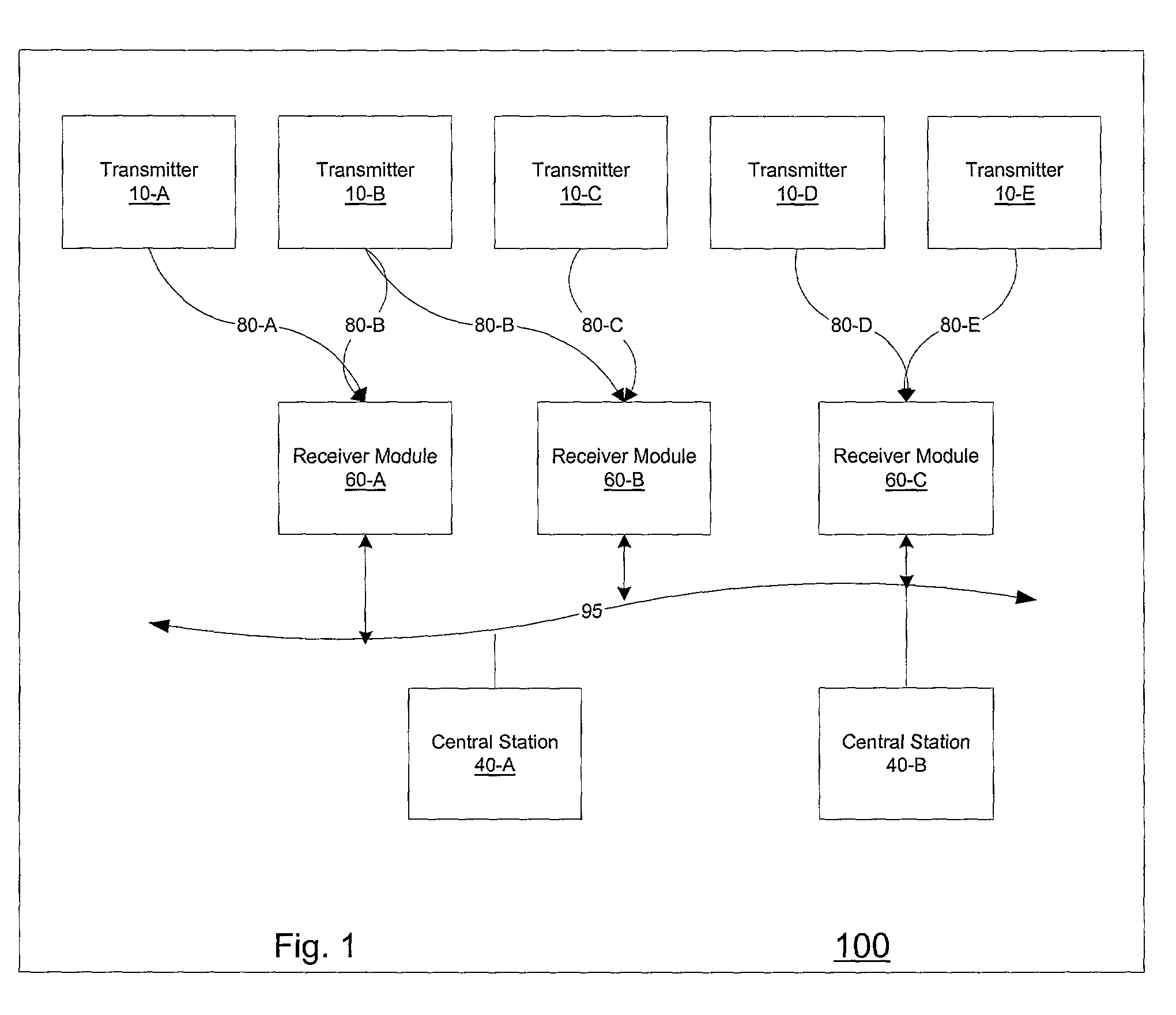
[0029]FIG. 1 illustrates a medical system 100 that comprises multiple transmitters (10A–10E), central stations (40A–40B), and receiver modules (60A–60C). As would be obvious to one skilled in the art, other monitors for gathering biomedical information, such as ECG devices, may be used in place of or with transmitters (10A–10E). Each transmitter (10A–10E) is connected to a patient to obtain and measure biomedical information from the patient. The obtained information is later transmitted to one or more central stations (40A–40B) for processing, storage, and display. In a preferred embodiment, the display on one central station may be replicated...


PUM


Abstract

The present invention relates to a system and method for simultaneously using and configuring one or more disposable transmitters. The system includes at least one single or multiple use disposable transmitter, a central station, and a receiver module. The transmitter is connected to a patient to gather and measure biomedical information. The transmitter transmits the biomedical information through the receiver module to the central station for processing, storage and display. Prior to use, each transmitter must be configured to work with the central station and the receiver module. This allows the users to configure the disposable transmitters relatively quickly and easily without needing advanced technical information. The inventive configuration also enables the operator to map a location on a monitor in the central station to a specific disposable transmitter and ultimately to a specific patient or location in the coverage area that is covered by the system.

Description

FIELD OF THE INVENTION[0001]This invention relates to medical monitoring systems, and more particularly to telemetry systems with disposable and / or reusable transmitters.BACKGROUND OF THE INVENTION[0002]In order to effectively monitor very ill patients, they often are connected to monitoring systems, such as telemetry systems. These systems generally include a number of monitors, such as ECG devices and reusable transmitters, for obtaining and measuring biomedical information from connected patients. Note that while different types of monitors are used in telemetry systems, typical systems using transmitters use reusable transmitters. Most reusable transmitters require replaceable and standardized batteries and electrodes to properly obtain and measure information from connected patients. Upon obtaining information from a connected patient, each reusable transmitter transmits the information to a central station, which receives information from multiple monitors and processes, displ...

Claims


Application Information

Patent Timeline
IPC IPC(8): G08B21/00A61B5/00H04M11/00
CPCA61B5/0002H04M11/002A61B2560/0271Y10S128/903A61B2560/0276
Inventor SWETLIK, DONALD EDWARDWHITTEN, ROBERT EDWARDPAUL, RICHARD BRIANEDSTROM, GARY BRUCEZEDNIK, GARY MICHAELDECASTRO, JR., CELSO OCHOACARR, ROY SEIZO
Owner MEDICAL DATA ELECTRONICS
Why Eureka
Try Eureka