Foundation drilling apparatus and method with continuously variable hydraulic differential rotary table

Inactive Publication Date: 2006-08-22
WATSON INC
View PDF11 Cites 15 Cited by
  • Summary
  • Abstract
  • Description
  • Claims
  • Application Information

AI Technical Summary

Benefits of technology

[0009]It is an object of the present invention to provide a rotary drive for a drilling machine that allows transition from high torque at

Problems solved by technology

In the prior art, drilling machines have had difficulty in transitioning the auger bit from drilling speeds to the higher spoil discharge speeds.
Unfortunately, without high torque, bringing the bit, loaded with spoil, from zero to high speeds is time consuming and sometimes ineffectiv

Method used


Image

  • Foundation drilling apparatus and method with continuously variable hydraulic differential rotary table
  • Foundation drilling apparatus and method with continuously variable hydraulic differential rotary table
  • Foundation drilling apparatus and method with continuously variable hydraulic differential rotary table

Examples


Embodiment Construction

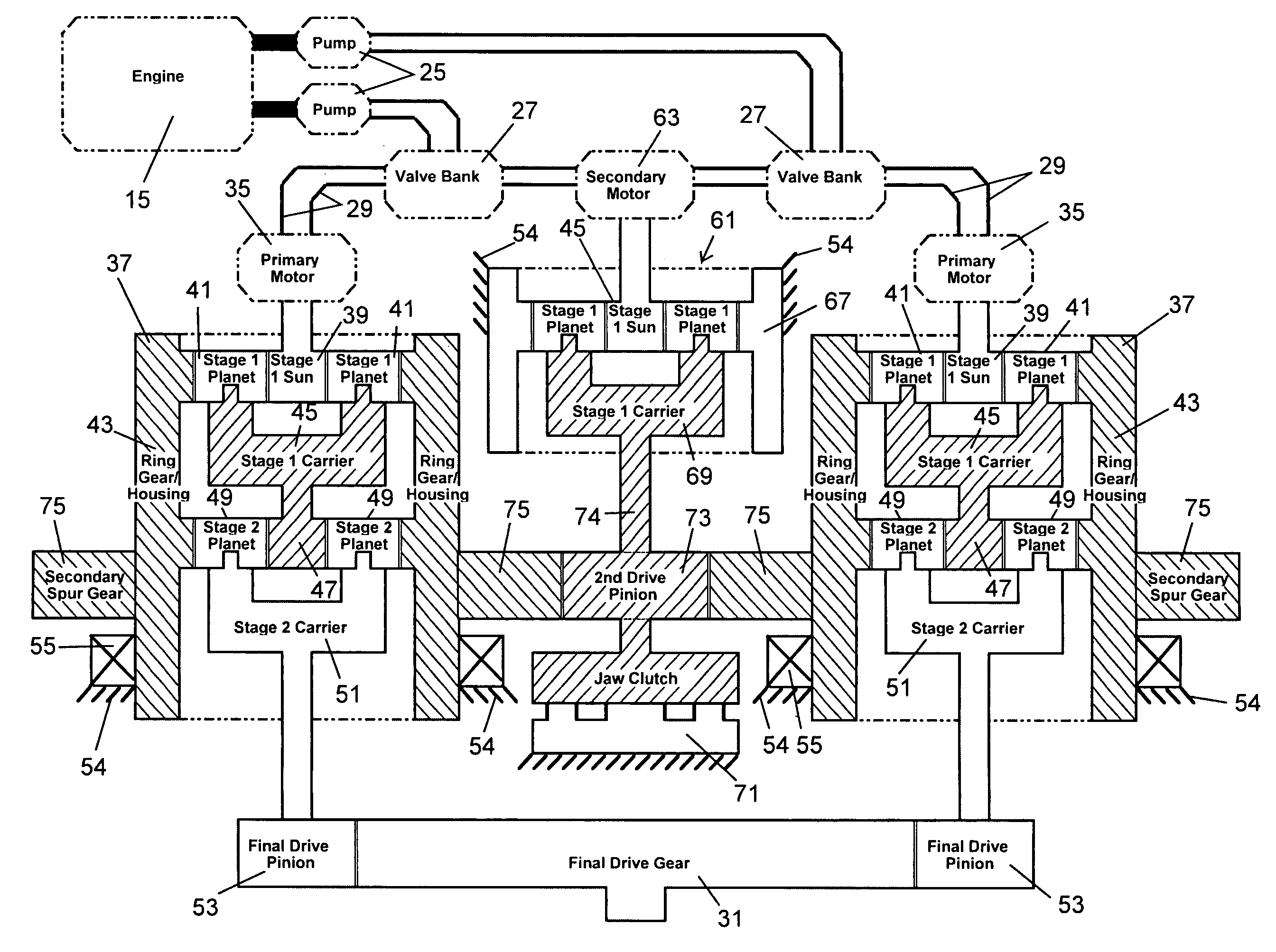
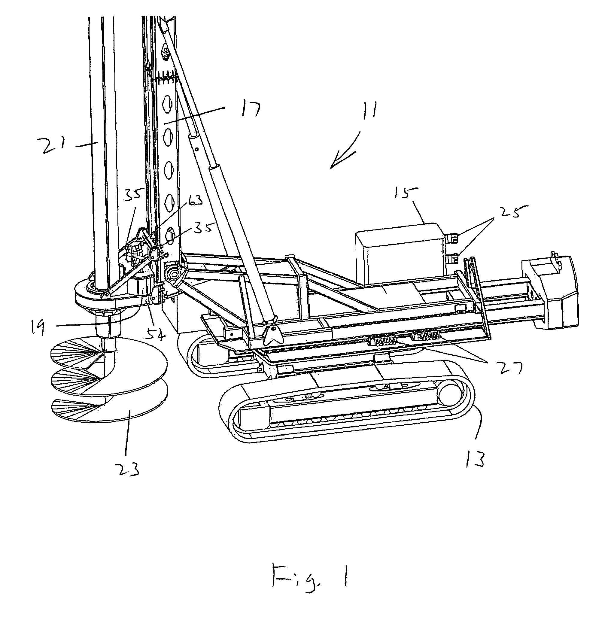
[0026]In FIG. 1, there is shown a drilling machine 11. The machine 11 is a self-propelled vehicle, being mounted on tracks 13 and having an engine 15. The engine 15 provides mechanical power to both propel the vehicle and conduct drilling operations. The drilling machine is used in drilled haft (bored pile) applications primarily used in the foundation industry.

[0027]At one end of the vehicle is a mast 17 that can be raised and lowered between a horizontal (stowed) position and a vertical (operational) position. Mounted to the mast 17 is a rotary drive 19. The rotary drive 19 can traverse along a portion of the length of the mast 17. The mast 17 has tracks and the rotary drive has guides that move along the tracks. Alternatively, the rotary drive can be fixed to the mast. The rotary drive 19 receives a kelly bar 21. Mounted to the bottom of the kelly 21 is a drilling tool, such as an auger 23. Other types of drilling tools can be used, such as core barrels, under reamers and drill b...


PUM


Abstract

A drilling machine drills foundation holes known as drilled shafts or bored piles with a drilling tool attached to an end of a kelly. The kelly is rotated with a rotary drive. The rotary drive has a first motor, a final drive gear coupled to the kelly so as to rotate with the kelly and a planetary gear set between the first motor and the final drive gear. A second motor is coupled to the ring gear on the planetary gear set. A clutch can also be connected to the ring gear. The rotary drive allows the drilling tool to be rotated at low drilling speeds and, without stopping rotation or shifting gears, removed from the hole and accelerated to high speeds to discharge spoil. A mid-range is also possible, wherein the drilling tool can process fluids in the hole. Another motor and planetary gear set can be coupled to the final drive gear and to the second motor.

Description

[0001]This application is a continuation-in-part of U.S. application Ser. No. 60 / 476,046, filed Jun. 5, 2003.FIELD OF THE INVENTION[0002]The present invention relates to rotary drives and methods for drilling and in particular to foundation or pier drilling.BACKGROUND OF THE INVENTION[0003]Foundation or pier drilling machines (also known in the industry as bored piling machines) are used to drill holes for the foundations of structures, such as buildings and bridges. The holes drilled may be, for example, up to 12 feet in diameter and up to an average of 120 feet deep. Once the hole is drilled, concrete is poured in to form a pier or footing.[0004]The drilling tool of choice is an auger bit. The auger has helical, spiraling flanges or flights.[0005]In typical drilling operations with an auger bit, the auger is placed onto the desired location in the ground and then rotated. Rotation of the auger occurs by rotating a kelly bar that is inserted into the auger. The kelly is coupled to ...

Claims


Application Information

Patent Timeline
IPC IPC(8): E21B3/02F16H47/02
CPCE21B7/021F16H61/452F16H47/04F16H3/72F16H2047/045
Inventor WATSON, DOUGLAS A.
Owner WATSON INC
Why Eureka
Try Eureka