Filter device for garden ponds or similar

a filter device and pond technology, applied in gravity filters, feed/discharge of settling tanks, loose filtering material filters, etc., can solve problems such as difficult cleaning, and achieve the effect of simple cleaning and not needing to be disassembled

Inactive Publication Date: 2006-08-22
OASE WUEBKER
View PDF8 Cites 5 Cited by
  • Summary
  • Abstract
  • Description
  • Claims
  • Application Information

AI Technical Summary

Benefits of technology

[0007]Therefore, it is the object of the present invention to provide a filter device of the type mentioned above which is simple to clean and does not need to be disassembled for the purpose of cleaning.

Problems solved by technology

Filter devices of this type have the disadvantage that they are difficult to clean.

Method used


Image

  • Filter device for garden ponds or similar
  • Filter device for garden ponds or similar
  • Filter device for garden ponds or similar

Examples


Embodiment Construction

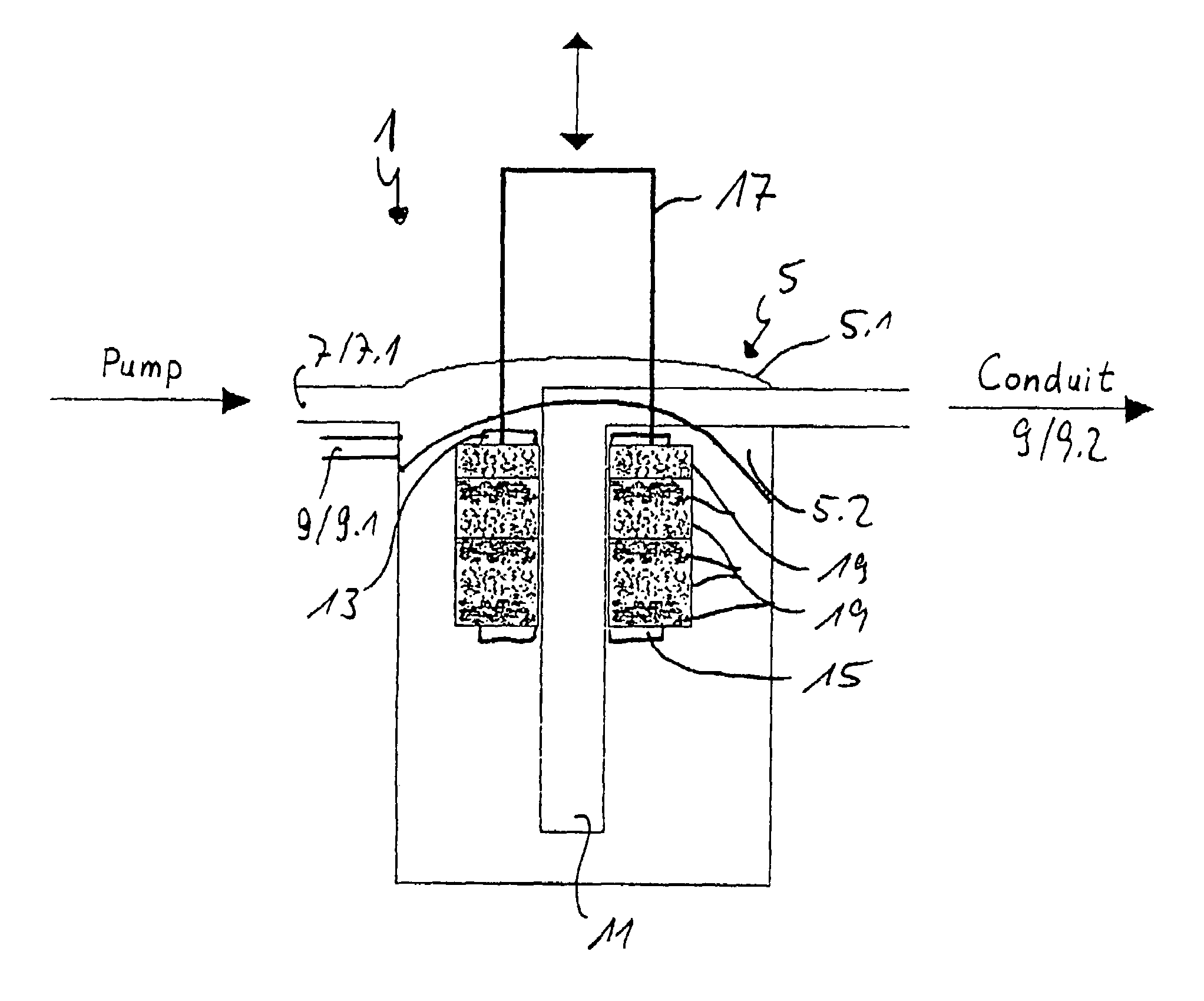
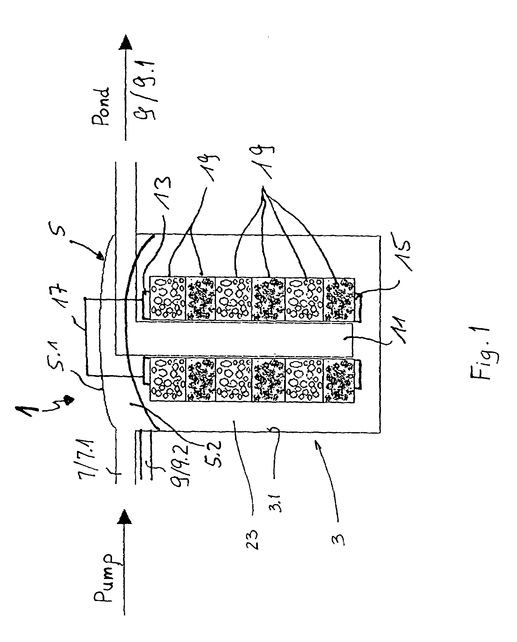
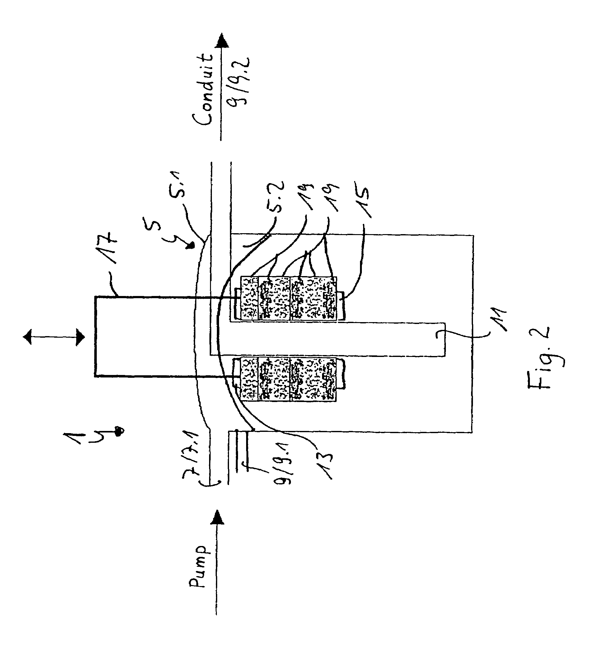
[0020]A filter device 1 comprises a vessel 3 and a vessel cover 5. An inlet area 7 and an outlet area 9 are formed in the vessel cover 5. The outlet area 9 comprises a first runoff opening 9.1 to a pond and a second runoff opening 9.2 to a conduit. The inlet area 7 comprises an inlet opening 7.1 which is connected to a pump by a hose, a line or the like and by which fluid, e.g., the pond water to be filtered, can be pumped into the filter device 1. A central flow conduit 11 is formed as a filter connection piece in the vessel 3, i.e., the circumference of the filter connection piece is slotted, perforated or the like to allow a flow of liquid from the filter medium 19 (described below) through the sides of the filter connection piece.

[0021]In the vicinity of the vessel cover 5, that is, at the top in FIG. 1, an upper, first holding surface 13 is arranged in a stationary manner proximate the upstream end of the central flow conduit 11. At the bottom, i.e., at a downstream end, of the...


PUM

PropertyMeasurementUnit
inlet areaaaaaaaaaaa
outlet areaaaaaaaaaaa
areaaaaaaaaaaa

Abstract

A filter device for filtering flowing liquids comprises a compressible filter medium in a vessel and a device by which the filter medium can be compressed by means of an actuation handle, so that impurities can be pressed out of the filter medium. In addition, the filter device contains a multipath regulator which can be adjusted for filtering, back-rinsing and clear-rinsing by means of three flow paths. It is also possible for the filter device to be outfitted exclusively with a multipath regulator or a compressing device.

Description

PRIORITY CLAIM[0001]This is a U.S. national stage of application No. PCT / DE02 / 03163, filed on 28 Aug. 2002. Priority is claimed on that application and on the following application(s): Country: Germany, Application No.: 101 42 092.7, Filed: 30 Aug. 2001.BACKGROUND OF THE INVENTION[0002]1. Field of the Invention[0003]The present invention is directed to a filter device for filtering flowing liquids including a vessel, a compressible filter medium which is arranged in the vessel along a central flow channel or conduit and between an inlet area and an outlet area in the main flow direction, and with a vessel cover in which the inlet area and the outlet area are integrated.[0004]2. Description of the Prior Art[0005]A filter device of the type mentioned above is known in general from the prior art. Filter devices of this type have the disadvantage that they are difficult to clean. The filter devices are used in ponds to filter suspended matter out of the pond water. Therefore, the filter...

Claims


Application Information

Patent Timeline
Patent Type & Authority Patents(United States)
IPC IPC(8): B01D25/00B01D24/00B01D29/15
CPCB01D24/004B01D29/15B01D24/08B01D24/4631B01D24/4668B01D29/668B01D29/70B01D2201/184B01D2201/186B01D2201/302B01D29/705
Inventor HOFFMEIER, DIETER
Owner OASE WUEBKER
Why Eureka
Try Eureka