Spirometer

a spirometer and spirometer technology, applied in the field of spirometers, can solve the problems of large user training, low cost of a standard spirometer, and inability to carry a standard spirometer, and achieve the effect of small and portable, easy and accurate use in the home environmen

Inactive Publication Date: 2006-08-22
ILLINOIS INSTITUTE OF TECHNOLOGY
View PDF22 Cites 37 Cited by
  • Summary
  • Abstract
  • Description
  • Claims
  • Application Information

AI Technical Summary

Benefits of technology

[0018]The spirometer of this invention is relatively small and portable, and can be easily and accurately used in a home environment. With the spirometer of this invention, patients can self-monitor between visits to the doctor. The spirometer of this invention eliminates the need for manual recording of respiratory or pulmonary data received as a result of daily monitoring.

Problems solved by technology

However, standard spirometers are relatively expensive and require significant user training for proper operation.
Standard spirometers are not portable and often require the user to own a computer to operate the spirometer.
However, the cost of a standard spirometer ranges from about $ US 2,000 to about $ US 10,000, and thus are not readily available or practical for daily home use.
Also, standard spirometers can become less accurate as respiratory flow rates become relatively low.
Patients with respiratory disease often can achieve only relatively low flow rates during exhalation, and thus the standard spirometer operates in a less accurate range.
The tubes can become clogged with the mucus debris, which further reduces the accuracy of the standard spirometer.
Also, such standard spirometers are difficult to clean and sterilize, primarily because they must be disassembled for thorough cleaning.
The calibration process is time-consuming and awkward.
However, monitoring spirometers are less accurate than standard spirometers.
Because home compliance is a significant problem with daily physical activities at home routines, manually recorded results are often inaccurate and result in an incorrect diagnosis.
However, information contained in the FEV1.0 value is not as useful to the physician as a graph of the time-volume curve for each day.
Most standard spirometers produce a time-volume curve but most monitoring spirometers do not produce a time-volume curve.
The maximum flow rate measurement provides relatively little useful diagnostic information.
However, some physicians believe that because diagnostic results obtained using a measure of peak flow rate are not worth the time, effort and expense involved, patients may avoid use of peak flow meters when performing daily tests.

Method used


Image

  • Spirometer
  • Spirometer
  • Spirometer

Examples


Embodiment Construction

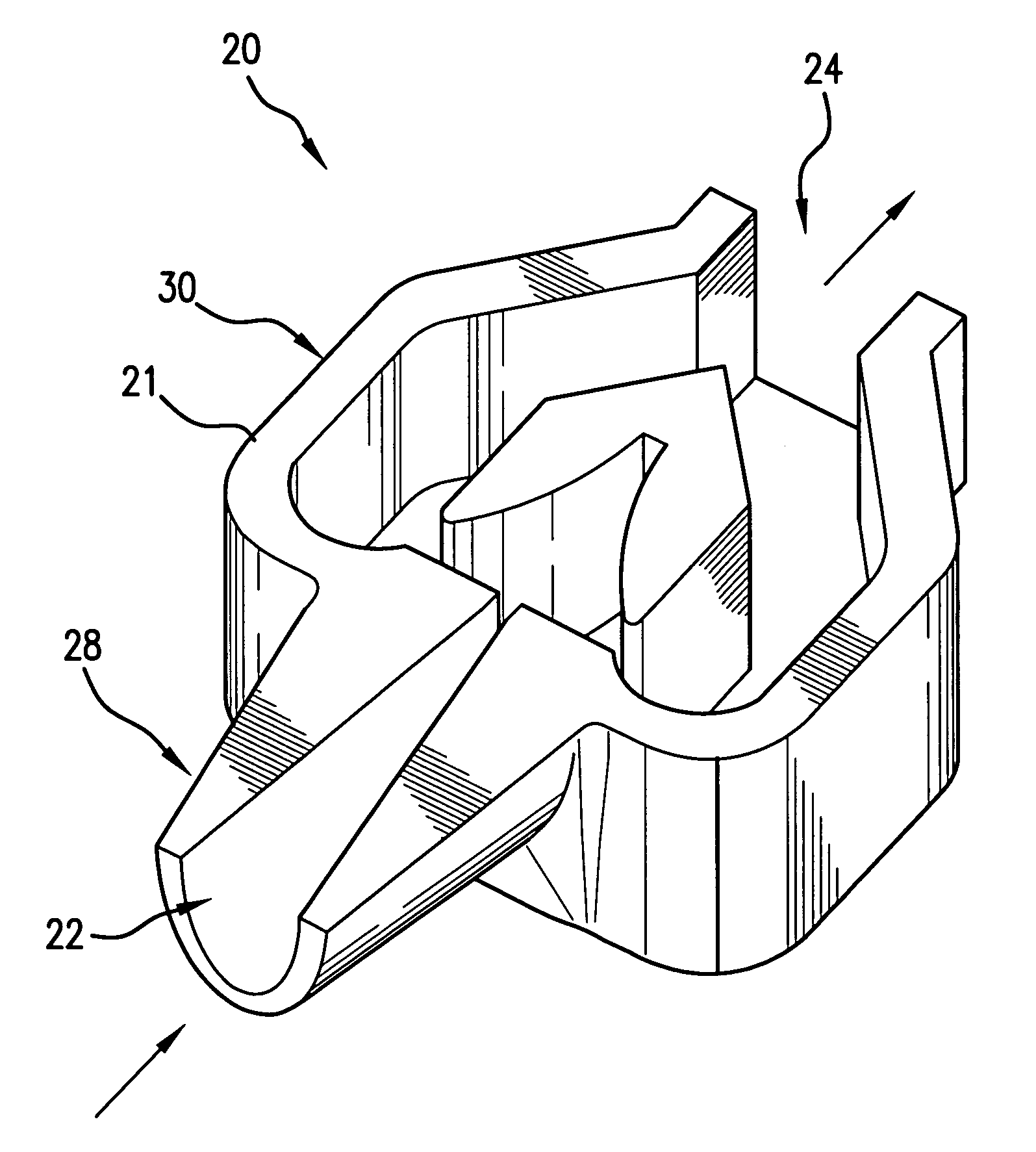
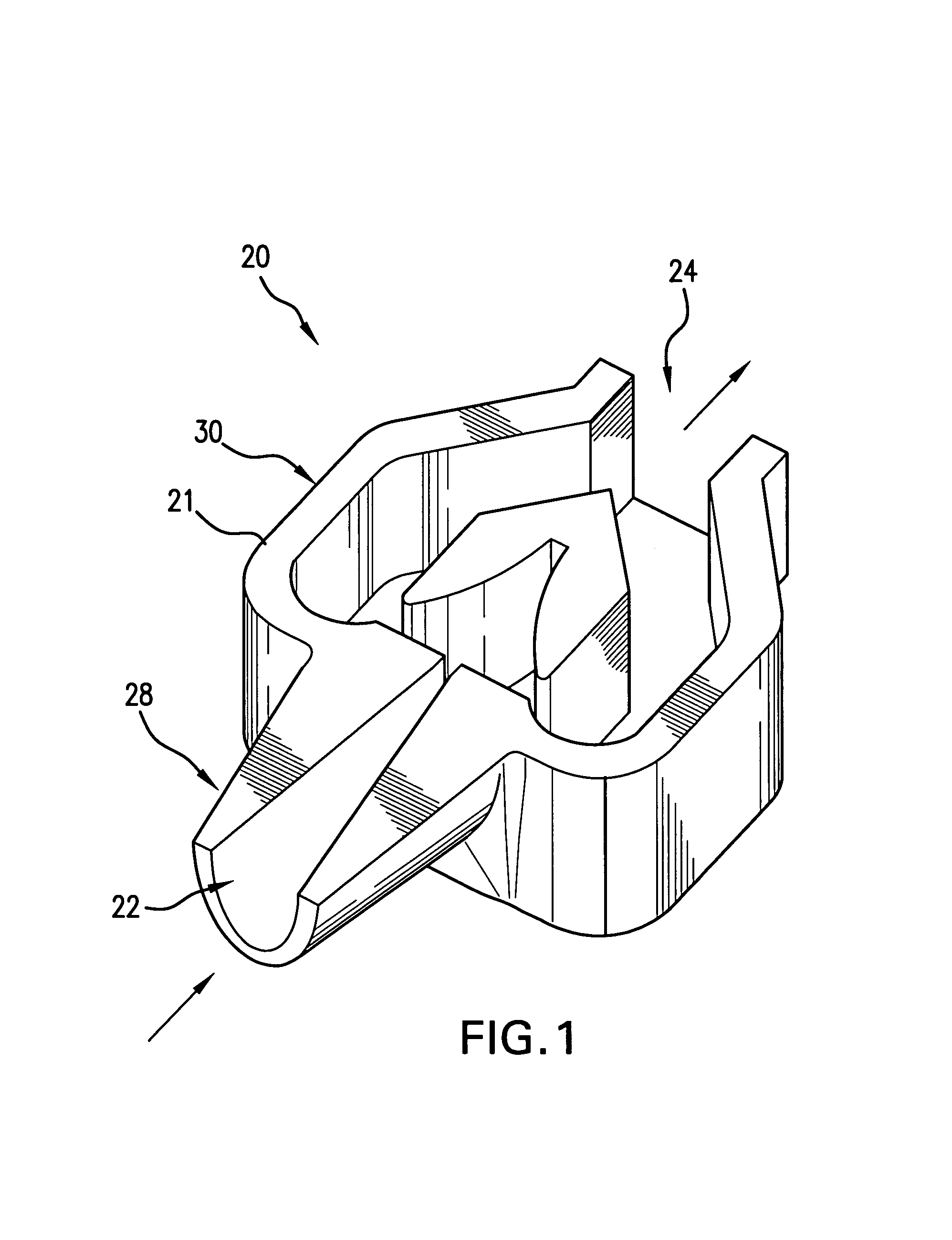
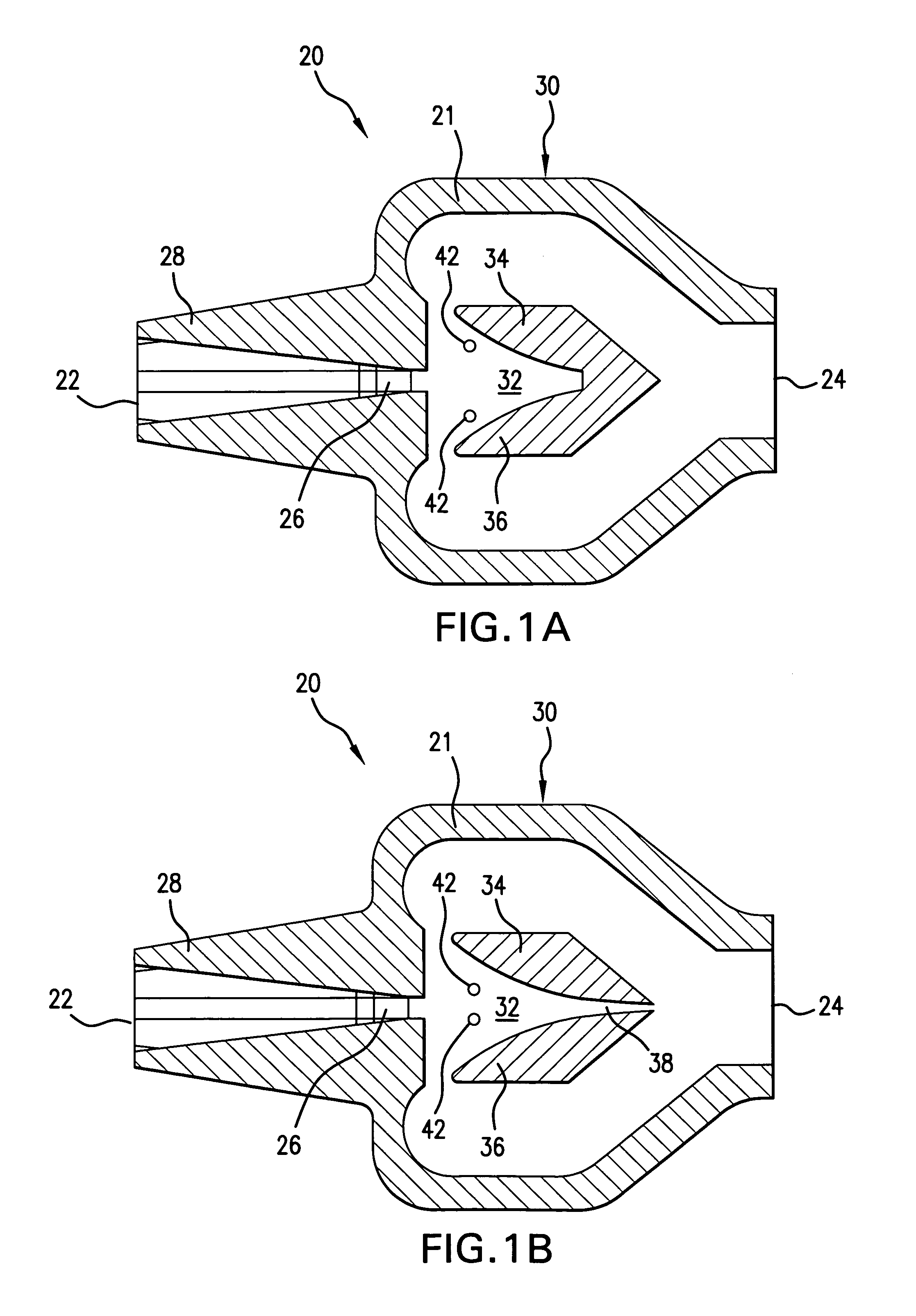
[0028]Spirometer 20 of this invention is a relatively small, preferably handheld device that operates using principles of oscillatory flow. Throughout this specification and in the claims, the word fluid is intended to relate to air or the fluidic content of an exhalation discharge from a patient, or any other similar fluid. The fluid enters spirometer 20 through inlet 22, and is ultimately discharged through outlet 24, as shown in FIGS. 1, 1A and 1B.

[0029]Mouthpiece 28 can be mounted directly or indirectly with respect to nozzle 26, so that the fluid flows through mouthpiece 28, through nozzle 26 and also through inlet 22.

[0030]According to one embodiment of this invention, spirometer 20 comprises a fluidic oscillator flowmeter. Conventional fluidic oscillator devices exist. For example, U.S. Pat. Nos. 4,843,889 and 5,363,704, the teachings of which are incorporated into the specification by reference to both United States patents, teach a fluidic oscillator, for example one that c...


PUM


Abstract

A spirometer for measuring fluid flow, particularly associated with exhalation of respiratory patients. The spirometer of this invention preferably has a fluidic oscillator wherein the fluid oscillates within a chamber of the fluidic oscillator. An oscillation frequency of the fluid flow within the chamber is correlated to a flow rate. A computer is used to process input data, such as data representing frequency of the oscillatory flow within the chamber, to a flow rate passing through the spirometer. The spirometer of this invention may have no moving parts, which results in the need for only a design calibration and no periodic calibrations throughout use of the spirometer.

Description

BACKGROUND OF THE INVENTION[0001]1. Field of the Invention[0002]This invention relates to a spirometer, particularly a fluidic oscillator spirometer, for measuring respiratory flow rates.[0003]2. Description of Related Art[0004]In the United States, the American Thoracic Society (ATS) sets guidelines and standards for treatment of people with respiratory disease. ATS guidelines suggest that lung function should be monitored regularly for patients with known respiratory disease. Patients use daily home monitoring of peak flow to periodically check respiratory flow.[0005]Patients and doctors use three main types of conventional devices to assess lung function: standard spirometers, monitoring spirometers, and peak flow meters. Standard spirometers, often used in a medical office, provide the most reliable results. However, standard spirometers are relatively expensive and require significant user training for proper operation. Standard spirometers are not portable and often require th...

Claims


Application Information

Patent Timeline
Patent Type & Authority Patents(United States)
IPC IPC(8): A61B5/08A61B5/087
CPCA61B5/087
Inventor WILLIAMS, DAVID R.WILSON, NICOLE APRILMEADE, KEVIN PHILIPMANSY, HANSEN A.
Owner ILLINOIS INSTITUTE OF TECHNOLOGY
Why Eureka
Try Eureka