Device for protecting a syringe needle

Inactive Publication Date: 2006-08-22
ASPEN GLOBAL
View PDF9 Cites 28 Cited by
  • Summary
  • Abstract
  • Description
  • Claims
  • Application Information

AI Technical Summary

Benefits of technology

[0006]The present invention aims to overcome these disadvantages and its main objective is to provide an injection device equipped with a safety end-piece for protecting the needle-protecting cap which permits easy removal of the latter and is not liable to damage the needle and affect the seal.
[0013]to pivot in the opposite direction, upon the removal of the protective end-piece, by a small angle determined by the abutment face of its upstream section, so as to increase the penetration of the point of each claw and totally immobilise the needle-protecting cap relative to the said protective end-piece.
[0016]removal of the protective end-piece, in the course of which the penetration of the point of each claw is increased, guaranteeing the entrainment of the needle-protecting cap.
[0017]It should, additionally, be noted that according to this principle, the presence of the upstream and downstream abutment faces is essential, since they lead to the limiting of the pivoting angle of each claw and guarantee the perfect engaging and maintaining of each claw point in the needle-protecting cap, despite the fact that the latter is made of a flexible material.
[0023]Since the natural movement for removal of the protective end-piece consists in subjecting the latter to a rotational movement accompanied by a tractive force, such grooves in which the frontal edges of the claws are lodged lead to the provision of a system of engagement which ensures the rotational locking of the needle-protecting cap inside the said protective end-piece.

Problems solved by technology

Although the use of such protective end-pieces allows the intended objectives to be met, they nevertheless have a major disadvantage in that they have to be force-fitted onto the cap so that the gripping means pass over the collar and tend, upon this fitting, to push away the said cap.
Now, the fact that the said cap is pushed away in this manner may have two unfortunate consequences.
Firstly, it may lead to damage to the end of the needle conventionally sticking into the cap.
Furthermore, it may cause the seal between the needle-protecting cap and the syringe nose to rupture at the sealing neck of the syringe.

Method used


Image

  • Device for protecting a syringe needle
  • Device for protecting a syringe needle
  • Device for protecting a syringe needle

Examples


Embodiment Construction

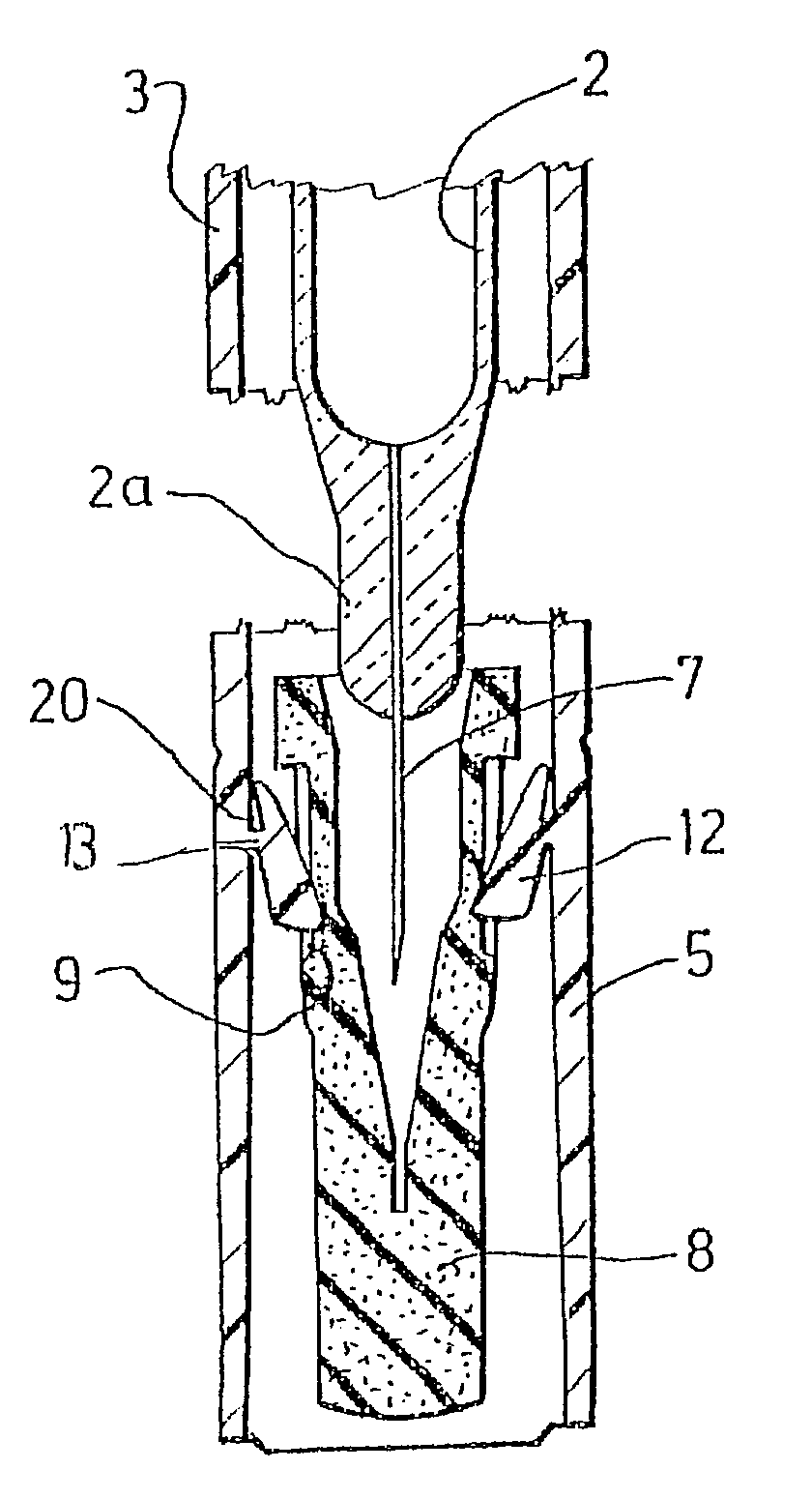
[0040]The protective device according to the invention is shown in the figures as forming an integral part of a single-use injection device having a syringe body 1 accommodating a prefilled syringe 2 and equipped with means for rotational and translational locking of the latter.

[0041]This injection device is of the type described in the patent applications FR-99,125000 and FR-99,12501, to which reference will be made for further details.

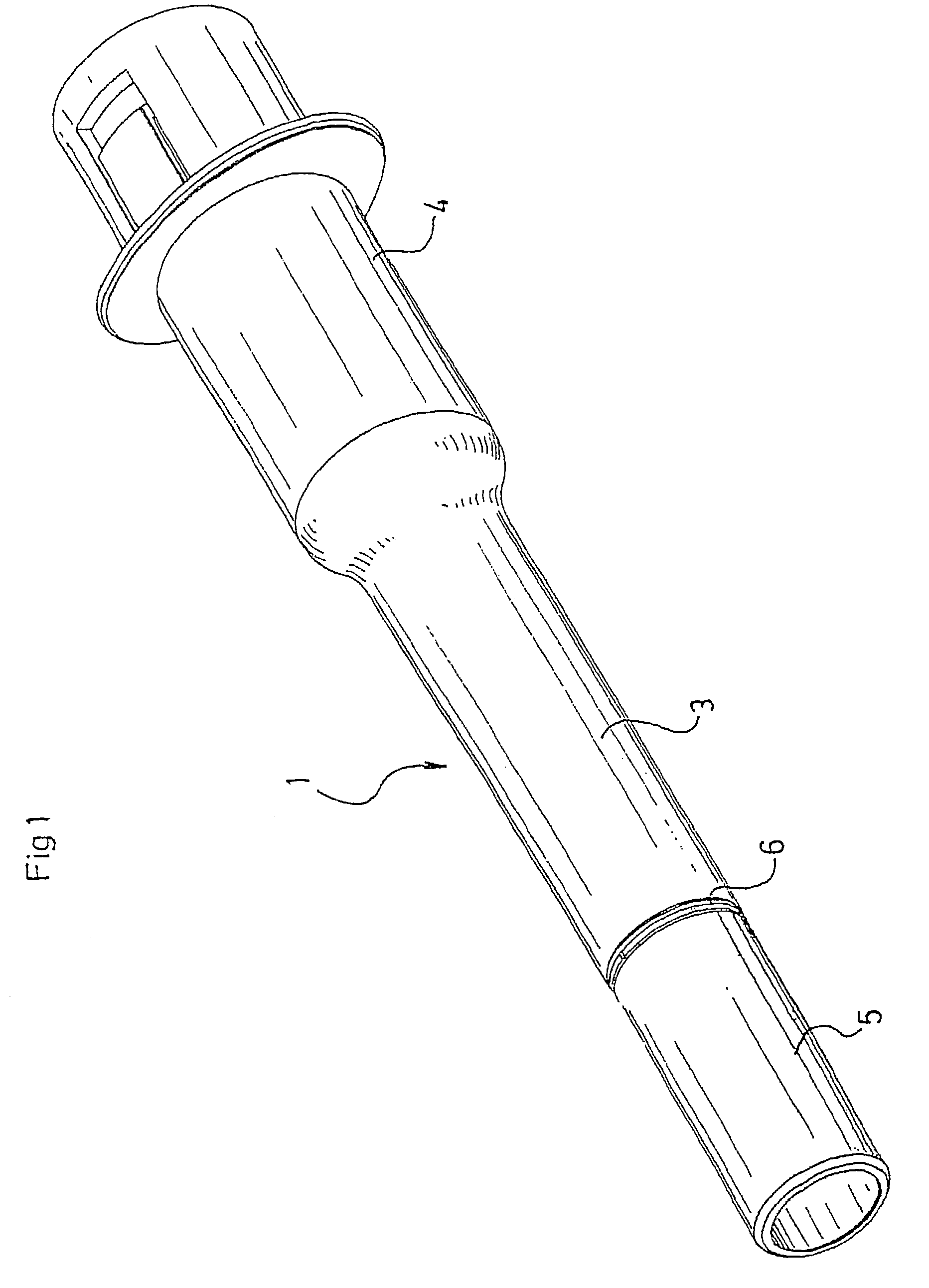
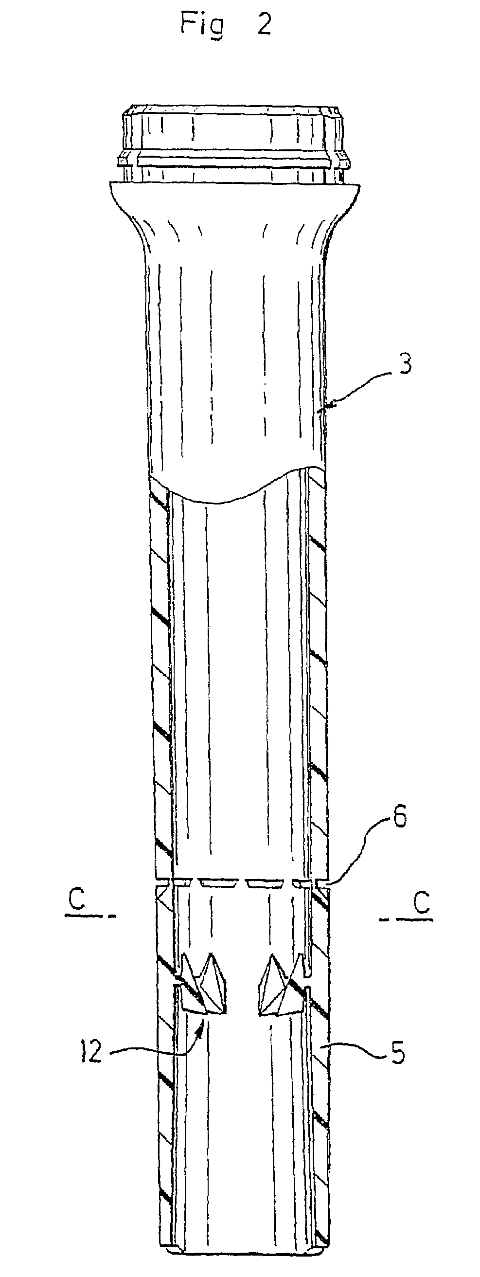
[0042]As described in these patent applications, this injection device comprises a syringe body consisting of a protective case 1, shown in FIG. 1, composed of two tubular bodies, anterior body 3 and posterior body 4, adapted to fit together as a continuation of one another, and to be preassembled before a conventional, initially prefilled syringe 2 is put in place in this protective case 1.

[0043]As also described in these patent applications, this injection device incorporates members, with elastic means, capable of bringing about the automatic with...


PUM


Abstract

A device for protecting a syringe (2) needle (7) comprising a needle-protecting cap (8) made of a flexible material and a protective hub (5) made of a rigid material adapted to be mounted on the needle-protecting cap (8) and provided with internal elements (12) for gripping the needle-protecting cap. The internal gripping elements provided in the protective hub (5) comprise at least a longitudinal clip (12) secured to the side wall of the protective hub (5) via a flexible intermediate hinge (13) forming an articulation longitudinally delimiting a downstream longitudinal section having a tip-shaped free end capable of being fitted into the needle-protecting cap (8) and comprising a front surface adapted to limit its tilting, and an upstream longitudinal section provided with a front surface adapted to limit reverse tilting of each clip (12) when the protective hub is removed.

Description

BACKGROUND OF THE INVENTION[0001]The invention is directed at a device for protecting a syringe needle, of the type having a needle-protecting cap made of a flexible material and a protective end-piece made of a rigid material adapted to cover the needle-protecting cap and equipped with internal means for gripping the said needle-protecting cap which are capable of entraining the latter upon the removal of the said protective end-piece.[0002]Such protective devices are commonly used and their main objective, apart from a notion of safety, is to facilitate the removal of the needle-protecting cap which is held within the protective end-piece upon the removal of the latter.[0003]In order to hold the needle-protecting cap, and in customary fashion, the protective end-pieces are equipped with gripping means adapted to be positioned behind the collar conventionally bordering the open end of the said needle-protecting caps, so as to abut against the said collar and cause the entrainment o...

Claims


Application Information

Patent Timeline
IPC IPC(8): A61M5/32A61M5/00A61M5/158A61M5/31
CPCA61M5/3202A61M2005/3109
Inventor BRUNEL
Owner ASPEN GLOBAL
Why Eureka
Try Eureka