Vertebral column support device which is assembled by means of clamping

a technology of supporting device and vertebrae, which is applied in the field of supporting device for vertebrae, can solve the problems of major risk of sliding member slipping and rotating on the securing rod, and the above device is not suitable for three-dimensional reduction of the upper portion of the spine, and achieves the effect of convenient fitting of the component parts

Inactive Publication Date: 2006-08-22
LAPE MEDICAL
View PDF24 Cites 39 Cited by
  • Summary
  • Abstract
  • Description
  • Claims
  • Application Information

AI Technical Summary

Benefits of technology

[0009]The problem addressed by the present invention is that of designing a new structure of a device for treatment of the spine with a smooth securing rod and anchor members in the form of sliding connecting members, which device secures the vertebrae much more effectively and greatly facilitates fitting the component parts and adjusting their relative positions in three dimensions. One particular aim is to allow the securing rod to be engaged with and disengaged from a sliding member already in position on a screw or other anchor member by lateral displacement.
[0022]To improve the rigid retention of the securing rod and facilitate lateral insertion of the securing rod into the sliding member, the thrust face has a plane lower portion oriented generally toward the bottom of the transverse groove to bear against the securing rod, and an upper portion open at the top to facilitate lateral engagement of the securing rod.

Problems solved by technology

The mechanical retention provided by the device is sometimes insufficient, however.
In particular, the fact that the sliding member bears directly on a vertebra rules out effective clamping, because vertebrae have poor mechanical strength in compression, as a result of which there is a major risk of the sliding member slipping and rotating on the securing rod.
Also, the above device is not suitable for three-dimensional reduction of the upper portion of the spine, where screws may not be implanted.
Furthermore, the clamping force of the nut significantly increases the traction stress exerted on the screw, being added to the securing force exerted by the securing rod, which reduces commensurately the mechanical strength of the anchorage and encourages necrosis of the bone around the screw.
Furthermore, when the sliding member is in position on the screw, it is no longer possible to engage the securing rod laterally in the sliding member.
This device, which seems suitable for adjusting the spacing of two successive vertebrae, is totally unsuitable for supporting more than two vertebrae, and there is no teaching regarding the problem of the insufficient mechanical retention of smooth securing rods.
What is more, when the sliding member is in position on the screw, it is no longer possible to engage the screwthreaded rod laterally.
The conical bearing surface of the nut, bearing on the cylindrical shape securing rod, cannot secure the securing rod sufficiently rigidly.
What is more, when the sliding member is fixed to the screw by the nut, it is no longer possible to engage the securing rod laterally.
Neither of these securing means provides sufficient rigidity.
For the same reasons as before, this does not provide sufficient rigidity.

Method used


Image

  • Vertebral column support device which is assembled by means of clamping
  • Vertebral column support device which is assembled by means of clamping
  • Vertebral column support device which is assembled by means of clamping

Examples


Embodiment Construction

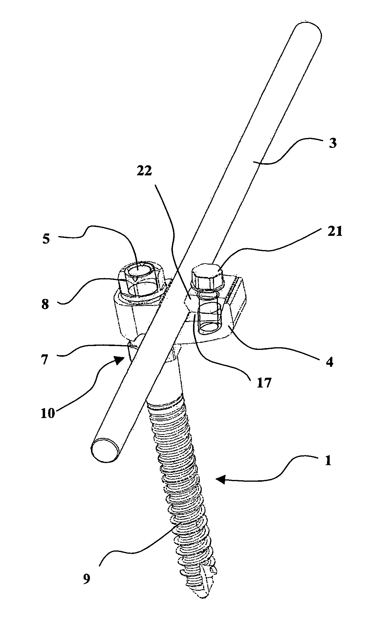
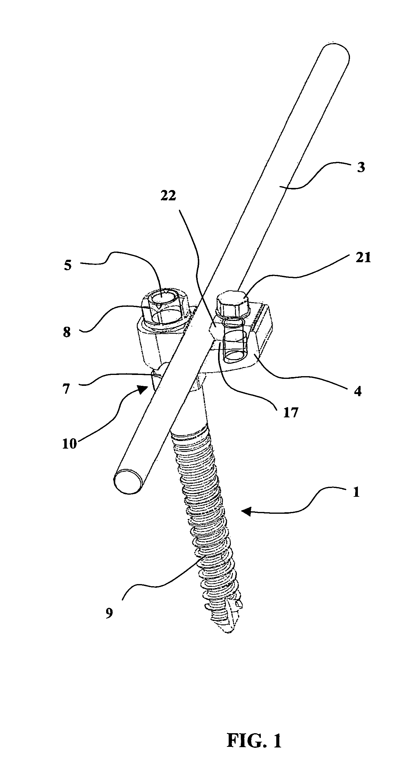
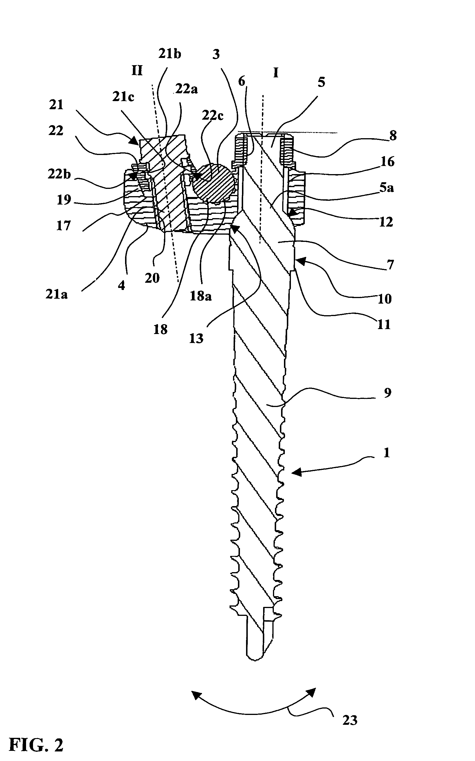
[0029]The device represented in the drawings comprises anchor members such as bone screws 1 (FIGS. 1 and 2) or hooks 2 (FIG. 3), securing rods 3, and sliding connecting members 4 between each anchor member and the securing rod 3.

[0030]The securing rods 3 of the device according to the invention are smooth circular section rods. The material and the section are selected to obtain optimum elasticity, matched to the forces to be encountered in use, and so that the rod can be curved to the required shape of the vertebral column portion to be treated.

[0031]Each anchor member, bone screw 1, hook 2 or bearing plate, is in one piece with a screwthreaded cylindrical portion 5 having an exterior screwthread 6, and comprises a stop flange 7 delimiting the screwing of a clamping nut 8 onto the exterior screwthread 6.

[0032]In the embodiment shown in FIGS. 1 and 2, the anchor member is a twin-thread bone screw 1, the cylindrical screwthreaded portion 5 with the exterior screwthread 6 constituting...


PUM


Abstract

A vertebral column support device is assembled by means of clamping. The device includes bone screw- or hook-type vertebrae anchoring elements, the elements consisting of a threaded cylindrical part (5) and a stop collar (7). A fixing nut (8) can be screwed on the threaded cylindrical part (5) in order to fix a connecting sliding piece (4) which is mounted on a securing rod (3) having a circular section. In order to insure that the rod (3) and the connecting sliding piece (4) are secure, the securing rod (3) is clamped in a transverse groove (17) in the connecting sliding piece (4) using a clamp screw (21) and a little clamp (22) which is mounted in the corner of the groove. In this way, the inventive device is more rigid and can better support the vertebrae and, moreover, the device can be positioned and adjusted much more easily.

Description

TECHNICAL FIELD OF THE INVENTION[0001]The present invention relates to a device for supporting vertebrae in a required position. A device of this kind is used to treat a spine having an abnormal deviation of degenerative or traumatic origin.[0002]For example, it is possible to treat vertebral fractures or arthroses, to correct vertebral column deviations such as scoliosis, lordosis and cyphosis.[0003]The document U.S. Pat. No. 4,648,388 discloses a device for treatment of the spine comprising members adapted to be anchored in the vertebrae, a circular section securing rod having a smooth exterior surface, and sliding connecting members for connecting the anchor members and the securing rod. The anchor members are screws having three main portions, namely a first end portion with a helicoidal screwthread adapted to penetrate and to be retained in bone, a smooth cylindrical intermediate portion of smaller diameter, and a second end portion with a helicoidal screwthread onto which a cl...

Claims


Application Information

Patent Timeline
Patent Type & Authority Patents(United States)
IPC IPC(8): A61B17/58A61B17/70
CPCA61B17/7041A61B17/70
Inventor GRADELCOTTIN, PHILIPPEJABY, YVESLEMAIRE, JEAN-PHILIPPE
Owner LAPE MEDICAL
Why Eureka
Try Eureka