Shielded wire harness

a shielding wire and wire harness technology, applied in the direction of insulated conductors, cables, coupling device connections, etc., can solve the problems of increasing the cost of the apparatus, increasing the number of parts and the number of assembling steps, and taking a lot of time and labor, so as to prevent the interference of objects colliding

Active Publication Date: 2006-08-22
AUTONETWORKS TECH LTD +2
View PDF19 Cites 73 Cited by
  • Summary
  • Abstract
  • Description
  • Claims
  • Application Information

AI Technical Summary

Benefits of technology

[0009]It is therefore an object of the invention to provide a wire harness which can prevent the interference of objects colliding thereto without increasing the number of parts.

Problems solved by technology

However, in the wire harness, an operation to insert the wire-side terminals into the shield case and an operation to connect the connecting members to the shield case must be repeated respectively the same number of times as the number of terminal poles (that is, the number of shielded wires), which takes much time and labor.
However, to provide the armored case separately from the wire harness causes a problem that not only the number of parts and the number of assembling steps increase but also the cost of the apparatus increases.

Method used


Image

  • Shielded wire harness
  • Shielded wire harness
  • Shielded wire harness

Examples


Embodiment Construction

[0017]Referring now to the accompanying drawings, a description will be given in detail of a preferred embodiment of the invention.

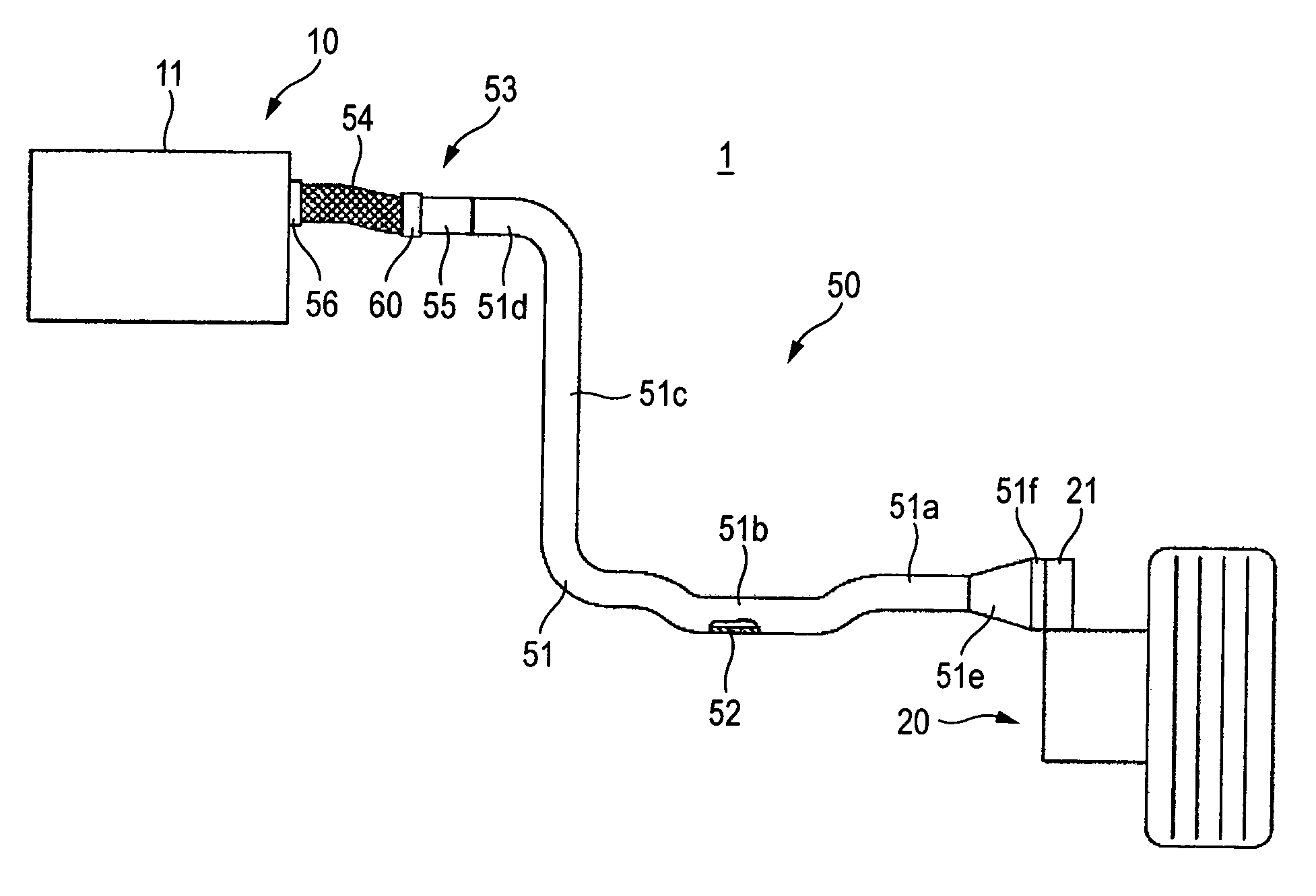
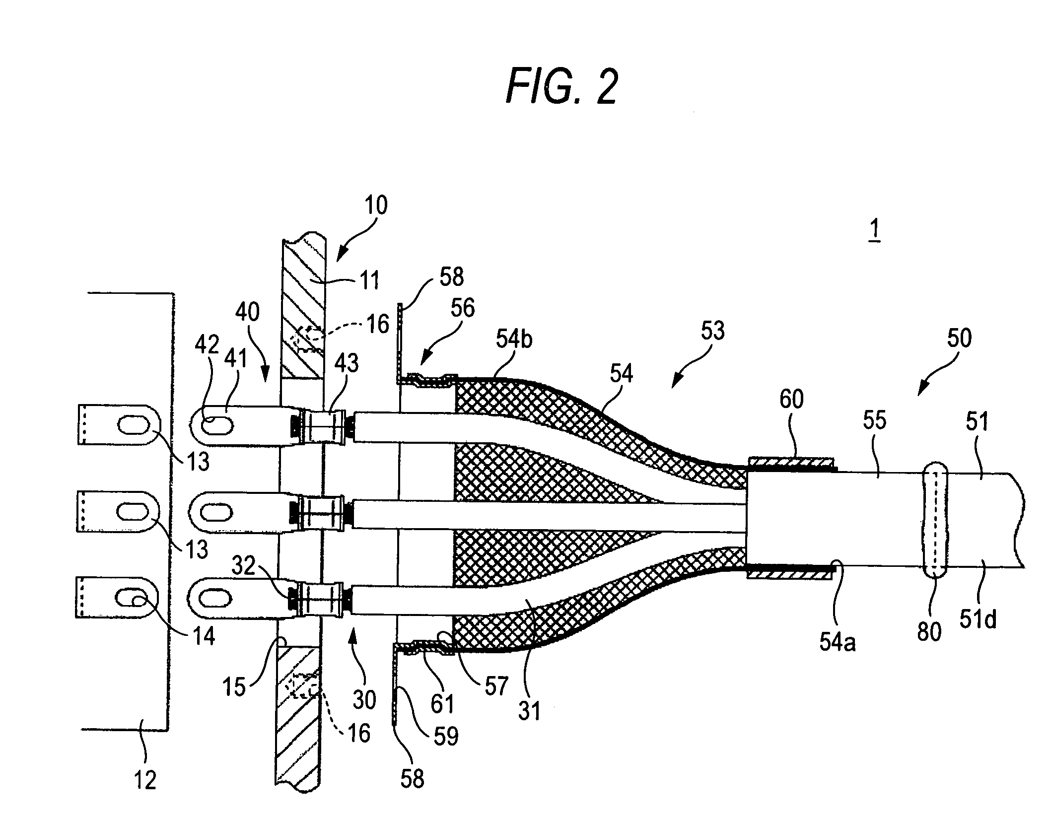
[0018]A shielded wire harness 1 according to an embodiment of the present invention, described with reference to FIGS. 1 through 5, is used for connecting an inverter unit 10 (as a first equipment) to a motor 20 (as a second equipment) respectively disposed in an electric vehicle.

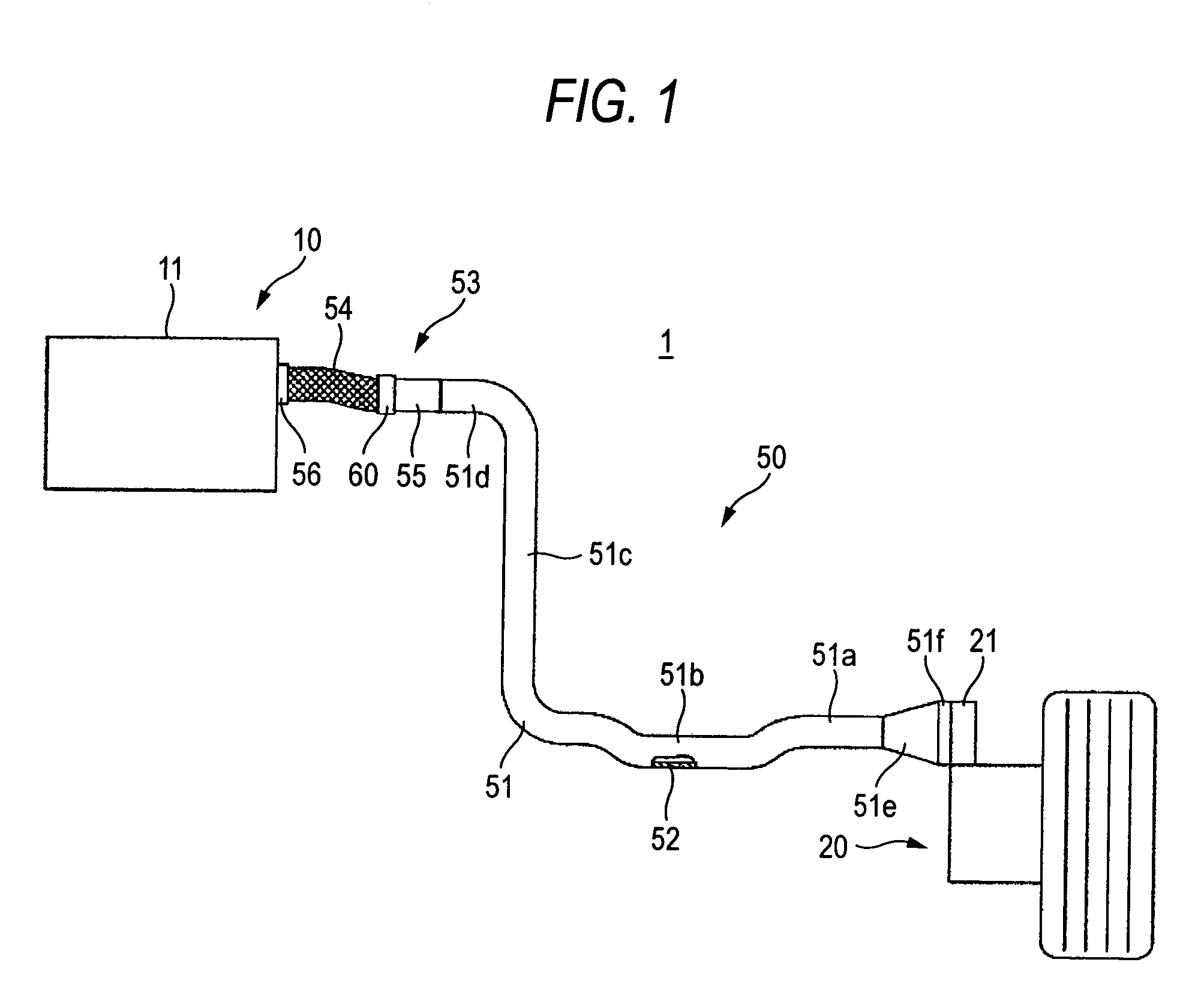
[0019]The inverter unit 10 is disposed in an engine room and is structured such that an inverter 12 and three equipment-side terminals 13 extended from the inverter 12 are stored in a conductive shield case 11. Each of the equipment-side terminals 13 is formed as a thick plate shape referred to as a bus bar and includes a bolt hole 14 which penetrates through the terminal in the vertical direction thereof. In the side wall of the shield case 11, there are formed three substantially-elliptic-shaped oblong mounting holes 15 so as to correspond to the three equipment-side terminals...


PUM

PropertyMeasurementUnit
shapeaaaaaaaaaa
conductiveaaaaaaaaaa
flexibleaaaaaaaaaa

Abstract

A tube-shaped shielding member is configured to enclose a plurality of wires collectively. The tube-shaped shielding member includes: a main shield portion made of a metal pipe; and a sub-shield portion formed shorter than the main shield portion and configured to be deformable, to thereby protect the wires from objects such as bounced stones.

Description

BACKGROUND OF THE INVENTION[0001]1. Field of the Invention[0002]The present invention relates to a shielded wire harness.[0003]2. Description of the Related Art[0004]For connecting machines such as an inverter unit and a motor in an electric vehicle, a shielded wire harness is used. As a wire harness of this type, there is known a wire harness structured such that wire-side terminals are fixed to the end portions of the conductors of shielded wires, the wire-side terminals are connected to equipment-side terminals disposed within a shield case of equipment, and the shield layers of the shielded wires are connected to the shield case through conductive connecting members (see JP-A-11-026093).[0005]However, in the wire harness, an operation to insert the wire-side terminals into the shield case and an operation to connect the connecting members to the shield case must be repeated respectively the same number of times as the number of terminal poles (that is, the number of shielded wir...

Claims


Application Information

Patent Timeline
Patent Type & Authority Patents(United States)
IPC IPC(8): H02G15/02H01R4/64H01B7/17H01B7/20H01R9/03H01R13/52H01R13/58H01R13/648H05K9/00
CPCB60L11/1803H01R9/032H01R13/5808B60L2220/46B60L2270/145Y02T10/7005H01R13/648H01R2201/26H01R13/5205B60L50/51H01R13/65912H01R2105/00Y02T10/70
Inventor KIHIRA, SOUJI
Owner AUTONETWORKS TECH LTD
Why Eureka
Try Eureka