Piezoelectric resonator

a resonator and piezoelectric technology, applied in piezoelectric/electrostrictive/magnetostrictive devices, piezoelectric/electrostrictive/magnetostriction machines, oscillator generators, etc., can solve problems such as reducing the size of electronic equipment, and achieve the effect of avoiding the risk of touching between the bonding wire and the external electrod

Active Publication Date: 2006-08-22
SEIKO EPSON CORP
View PDF15 Cites 21 Cited by
  • Summary
  • Abstract
  • Description
  • Claims
  • Application Information

AI Technical Summary

Benefits of technology

[0012]In recent years, as mounting technology has been enhanced more and the performance of electronic equipment has been heightened, piezoelectric resonators have come to be mounted on substrates with their direction aligned uniformly. The piezoelectric resonators have come to be shipped with their direction held uniformly. In recent years, therefore, consideration for the electrical directivity of the piezoelectric resonator in the mounted state thereof has been relieved. The present invention has been made in view of the above circumstances, and makes a substantial mounting area smaller.
[0013]According to a first aspect of the invention, the above is accomplished by a piezoelectric resonator, at least four external electrodes which are joined to patterns on a substrate side being disposed at an outer surface of a bottom of a package in which a piezoelectric resonator element is accommodated; and one pair of adjacent external electrodes among the external electrodes being electrically connected to electrodes of the piezoelectric resonator element. According to the construction of the first aspect of the invention, the external electrodes to which one pair of connection electrodes of the piezoelectric resonator element are connected are set as the adjacent ones of the four external electrodes, the pair of external electrodes can be arranged near an IC disposed on a substrate. Accordingly, a wiring pattern need not be formed along the piezoelectric resonator element for the purpose of electrically connecting the IC of the substrate and the external electrode of the piezoelectric resonator, the substantial mounting area of the piezoelectric resonator can be made smaller, and reduction in the size of electronic equipment can be coped with. Moreover, since the wiring pattern need not be provided along the piezoelectric resonator, the parasitic capacitance of the piezoelectric resonator can be lowered, and oscillation characteristics can be enhanced.
[0014]In the construction of the first aspect of the invention, in a second aspect of the invention t the pair of external electrodes electrically connected to said piezoelectric resonator element are disposed along a shorter latus of the package. According to the construction of the second aspect of the invention, in a case where the piezoelectric resonator has been reduced in size, the region (area) of the resonant part of the piezoelectric resonator element constituting the piezoelectric resonator can be set large, and a piezoelectric resonator of high performance can be obtained.
[0017]In the construction of the fourth aspect of the invention, in a fifth aspect of the invention at least one of the other pair of external electrodes is formed at only a position extending along an outer edge of the package. According to the construction of the fifth aspect of the invention, at least one, of the other pair of external electrodes is / are formed at only the position / positions extending along the outer edge of the package. Then, in such a case where an oscillation circuit element or the like is to be mounted on the bottom surface of the package, there is the advantage that unnecessary short-circuiting, etc. does not occur, so a space for the mounting can be larger.
[0020]According to the construction of the seventh aspect of the invention, in a case where the oscillation circuit element accommodated in the second package is electrically connected by wire bonding in a mounting operation, there is a possibility that bonding wire for the wire bonding comes in contact with the external electrode of the first package stacked on the second package. When the external electrode is formed at only the position extending along the outer edge of the first package, as in the seventh aspect of the invention, the risk of the touch between the bonding wire and the external electrode is avoided.

Problems solved by technology

This forms an obstacle to reduction in the size of electronic equipment.

Method used


Image

  • Piezoelectric resonator
  • Piezoelectric resonator
  • Piezoelectric resonator

Examples


Embodiment Construction

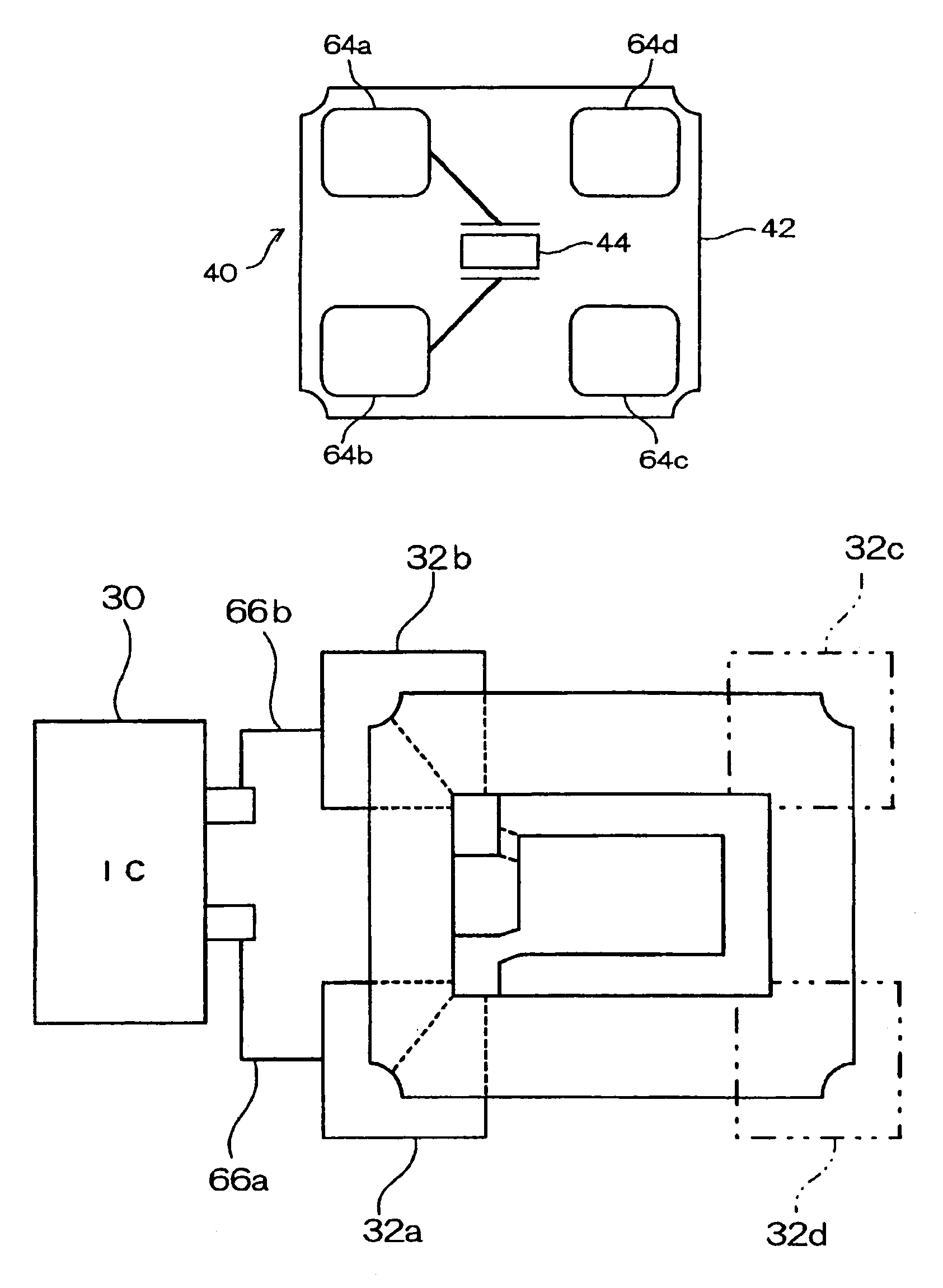
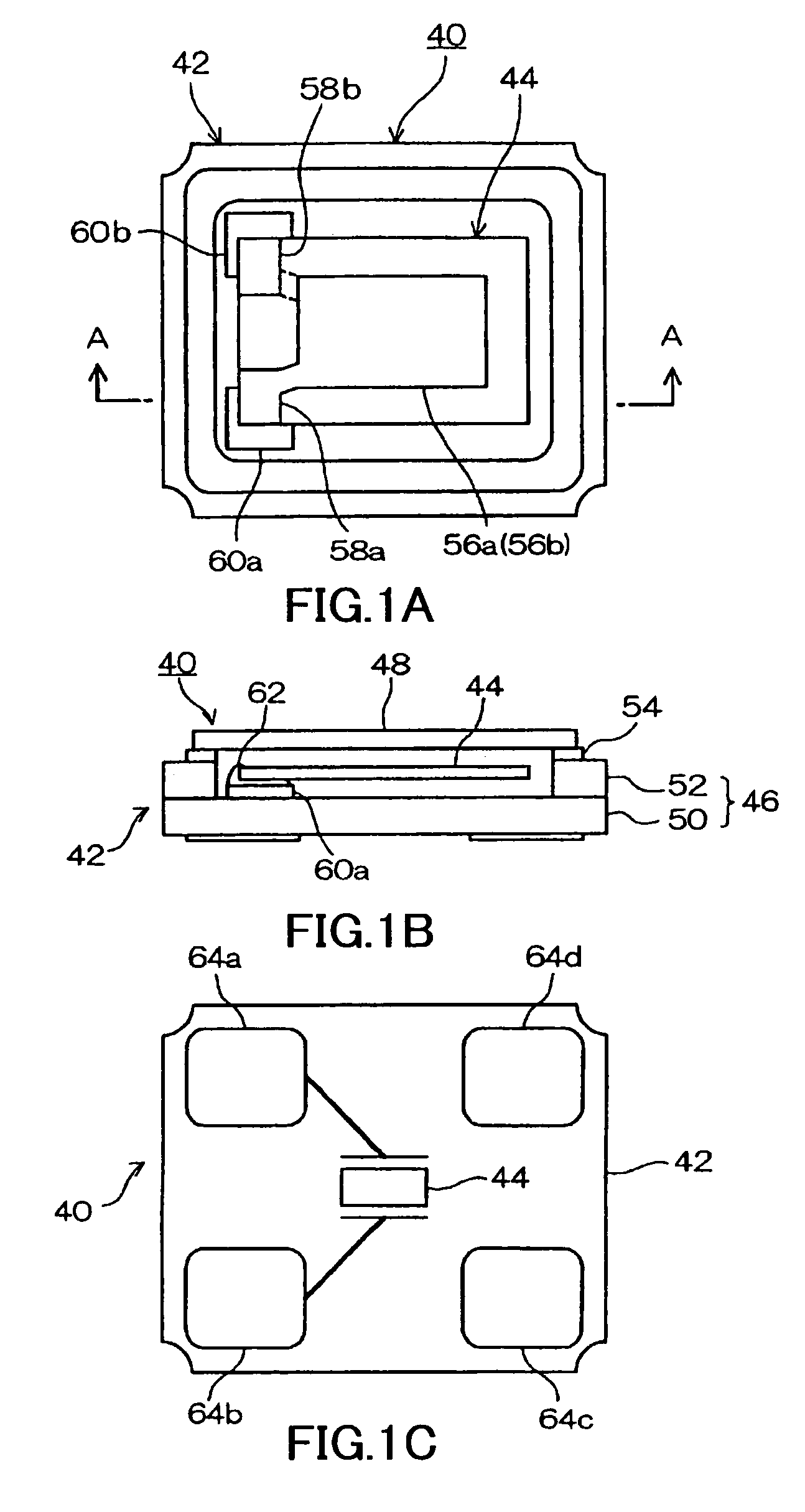
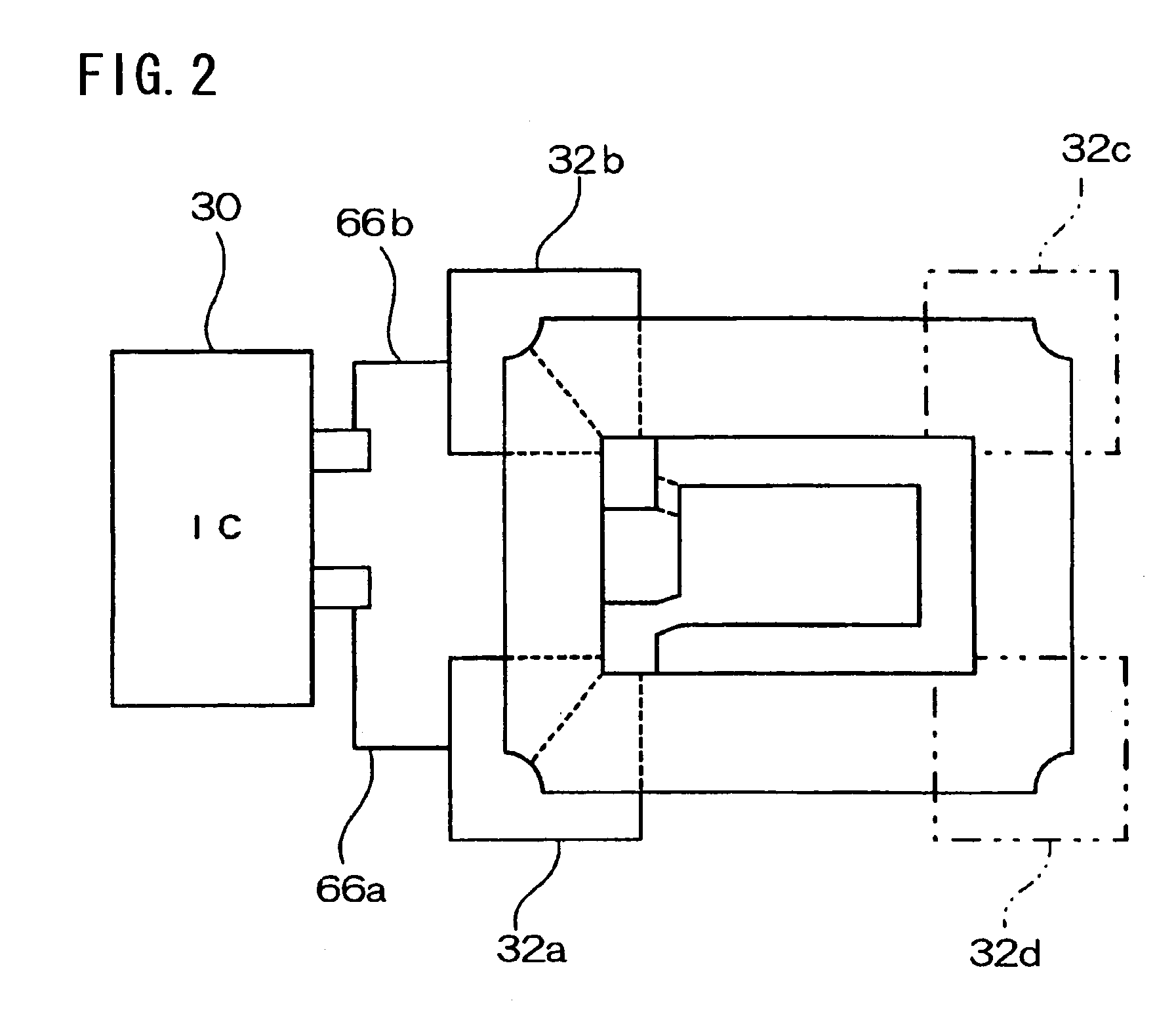
[0032]Exemplary embodiments of a piezoelectric resonator according of the present invention will be described in detail with reference to the accompanying drawings. FIG. 1 shows schematics of the piezoelectric resonator according to an aspect of the present invention, wherein A is a plan view of the piezoelectric resonator with a cover member omitted therefrom. B is a sectional schematic taken along plane A—A in 1, in a state where the piezoelectric resonator includes the cover member. C is a bottom view. Referring to FIG. 1, the piezoelectric resonator 40 has a structure in which a piezoelectric resonator element 44 is accommodated in a package 42. As shown in FIG. 1B, the package 42 includes a package body 46 and a cover member 48. The package body 46 has a double-layer structure which is constructed of a flat base sheet 50 that forms a bottom portion and a frame-like sheet 52 that is stacked on the base sheet 50. The base sheet 50 and the frame-like sheet 52 are made of an insula...


PUM


Abstract

To make a substantial mounting area smaller. A piezoelectric resonator has a piezoelectric resonator element accommodated in a package. The piezoelectric resonator element includes a pair of connection electrodes which are connected to excitation electrodes. The respective connection electrodes are joined to mount electrodes formed in the package. The piezoelectric resonator includes four external electrodes at the outer surface of the bottom of the package. The external electrodes disposed along the shorter latus of the package on one side in the lengthwise direction thereof are electrically connected with the mount electrodes to which the respective connection electrodes of the piezoelectric resonator element are connected.

Description

BACKGROUND OF THE INVENTION[0001]1. Field of Invention[0002]The present invention relates to a piezoelectric resonator. More particularly, it relates to a piezoelectric resonator in which four external electrodes are disposed on the outer bottom surface of a package, and a piezoelectric oscillator which utilizes the piezoelectric resonator.[0003]2. Description of Related Art[0004]Piezoelectric resonators are extensively employed in various electronic equipment including a communication apparatus, an electronic computer, etc. Typically, the piezoelectric resonator has a structure in which a piezoelectric resonator element made of a piezoelectric material, such as quartz, is accommodated in a package. The piezoelectric resonator has been made smaller and thinner in correspondence with the smaller and thinner construction of electronic equipment. The surface mount type of piezoelectric resonator has come into wide use in recent years. The piezoelectric resonator of the surface mount ty...

Claims


Application Information

Patent Timeline
Patent Type & Authority Patents(United States)
IPC IPC(8): H03H9/17H03B5/32H01L41/053H03H9/02H03H9/05H03H9/10H03H9/13H03H9/15
CPCH03H9/0542H03H9/1021H03H9/0547
Inventor UNNO, YUKIHIROMIYAZAKI, KATSUHIKO
Owner SEIKO EPSON CORP
Why Eureka
Try Eureka