Torque guarantee system

Inactive Publication Date: 2006-08-29
HONDA MOTOR CO LTD
View PDF10 Cites 30 Cited by
  • Summary
  • Abstract
  • Description
  • Claims
  • Application Information

AI Technical Summary

Benefits of technology

[0005]Devices have also been developed with features that attempt to control or limit torque. For example, fastener tightening tools exist that provide for automatic operation of the tool under certain conditions, such as the depression of a fastener engaging portion thereof. Other known fastener tightening tools have been designed to terminate the tightening operation upon detection of a preselected torque value, such as by disengaging a motor from a driver portion of the device or by automatically shutting off power to a drive motor. Such tools commonly use sensors, clutches or various other detection means to determine when the predetermined torque value has been reached. Yet other torque applying tools are adapted to monitor the pressure of a supply of air connected thereto and to shut off the air flow if the pressure falls below a preset level. In this manner, consistent operation of the tool is said to be achieved. Still other torque applying tools are provided with safety switches that must be engaged along with a primary device initiator, such as a trigger, before the tool will operate. These safety switches are provided to prevent premature activation of the tool to which they are installed.
[0013]Therefore, as can be understood from the foregoing description, interlocks are provided that direct the process of interest to be performed in a particular manner. Data provided to and from the system controller and / or torque monitor / controller ensures that a torque applying tool automatically tightens a particular fastener with a specific and predetermined amount of torque. For example, in the latter of the particular processes described above, the fasteners that are to be installed with a lesser amount of torque are also of a different size. Thus, when a provided socket or other fastener engaging means is installed to the torque applying tool, the torque applying tool is automatically set by the torque monitor / controller to install the fastener with the proper amount (lesser amount, in this case) of torque. Consequently, the system controller is able to determine whether all the necessary process steps were completed and that they were completed in the correct order and, through the torque monitor / controller, is able to detect the number of fasteners that have been installed and the amount of torque with which each fastener was installed—thereby enabling the system and method of the present invention to accurately determine whether the overall fastener(s) installation process was successful.

Problems solved by technology

For example, if a fastener is overtightened, it may cause unnecessary and undesirable fatigue in the fastener, and / or may damage the component(s) through which it passes.
Conversely, if the fastener is to secure a component(s) that will be subjected to a load, to vibration, or to other similar conditions, loosening of the fastener and the component(s) may occur if the fastener is not adequately tightened.
As can be appreciated, there are numerous components, particularly those relating to the engine, suspension, steering and other motive systems of such a vehicle, that could cause serious problems or damage if allowed to loosen during vehicle operation.
For example, an operator may accidentally mark a fastener that was not tightened appropriately, or that was not subsequently checked.
None of the aforementioned tools, however, is able to guarantee that a particular fastener, or number of fasteners, has actually been installed with a specific amount of torque.
Thus, even if a fastener is subsequently indicated by an operator as being properly torqued, there is no non-human guarantee that such is the case.
Again, however, the possibility for human error is obvious.
For example, it may be indicated that one or more fasteners were not tightened, were not tightened with an adequate amount of torque, or were tightened with an excessive amount of torque.

Method used


Image

  • Torque guarantee system
  • Torque guarantee system
  • Torque guarantee system

Examples


Embodiment Construction

)

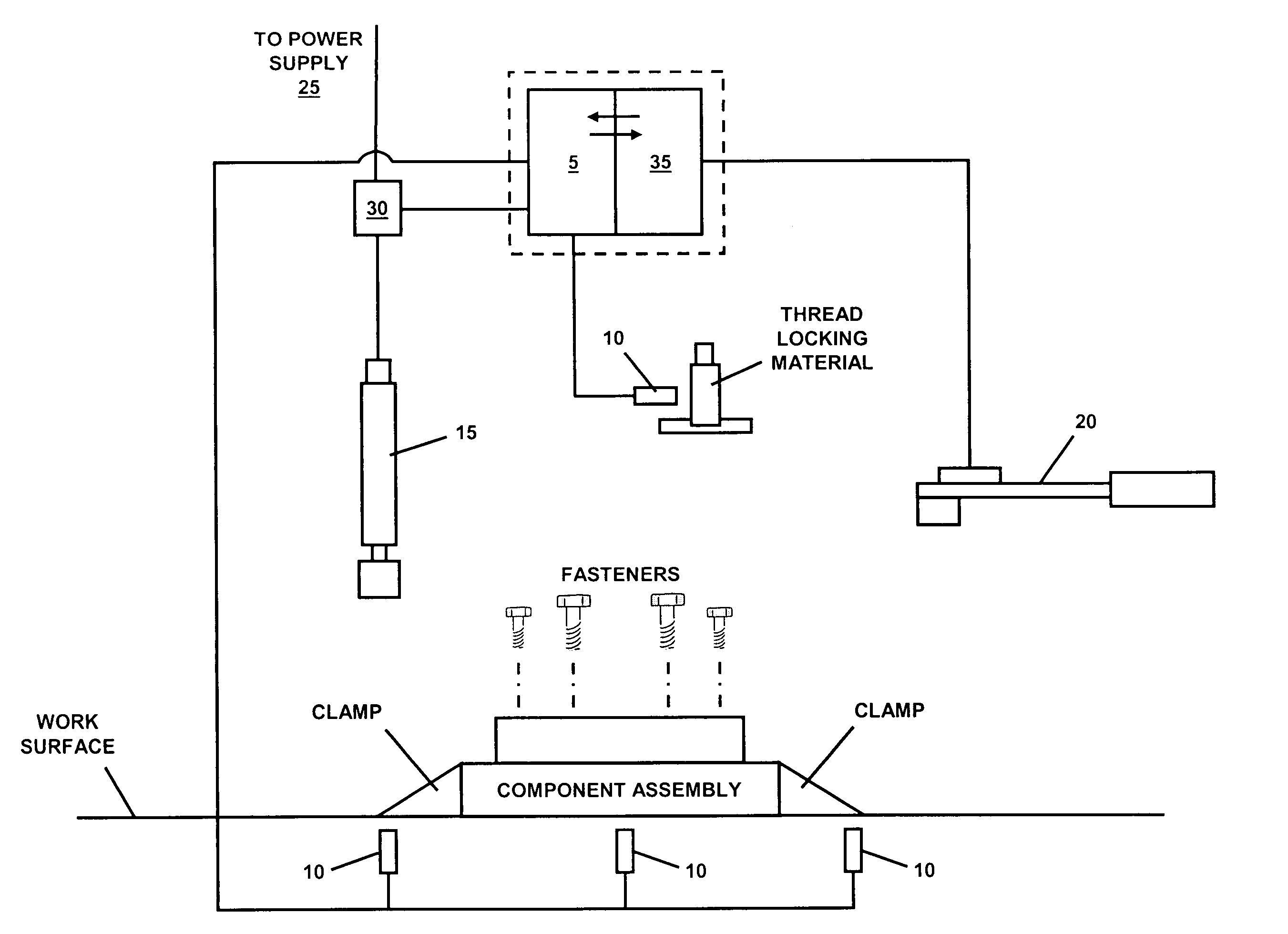
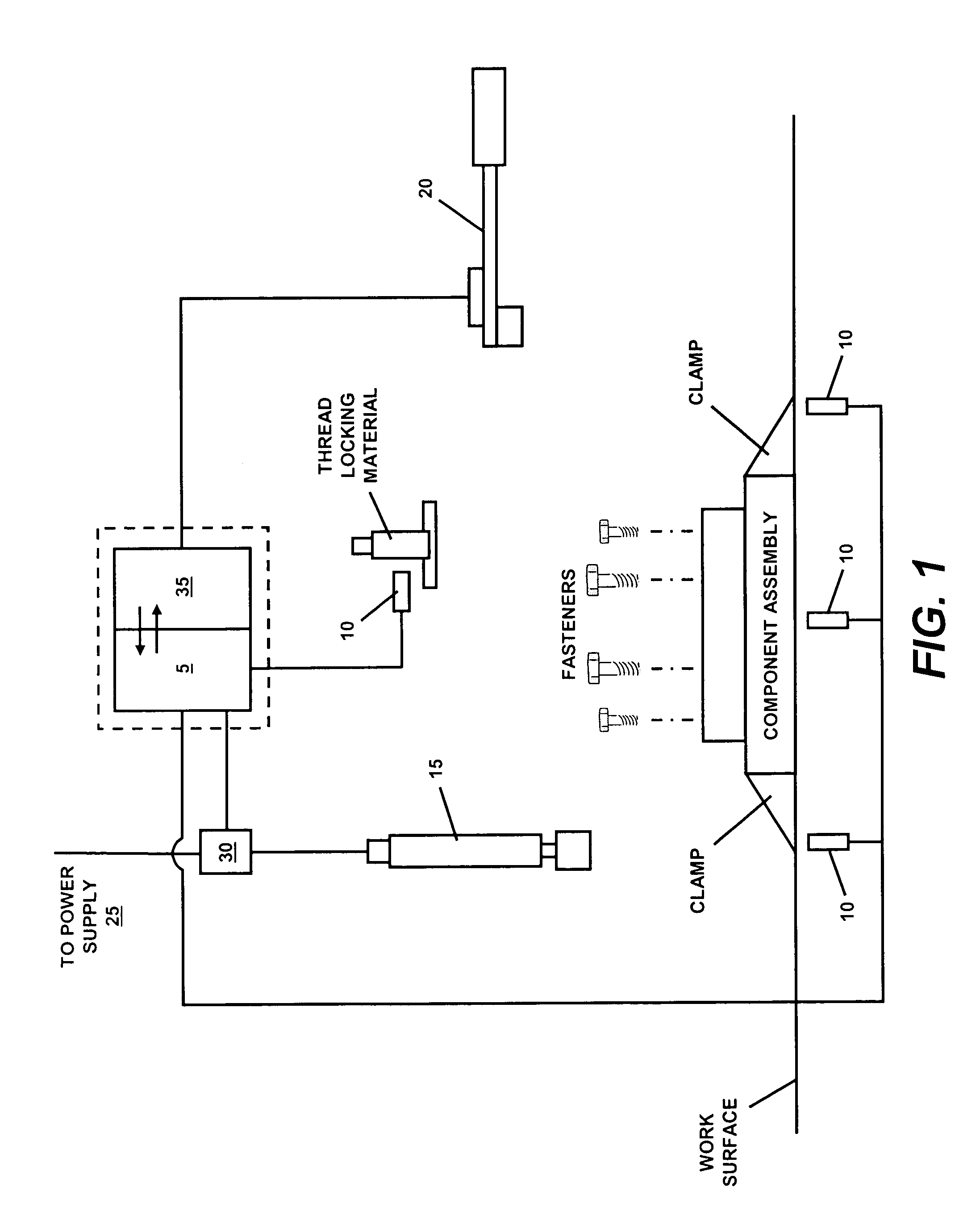
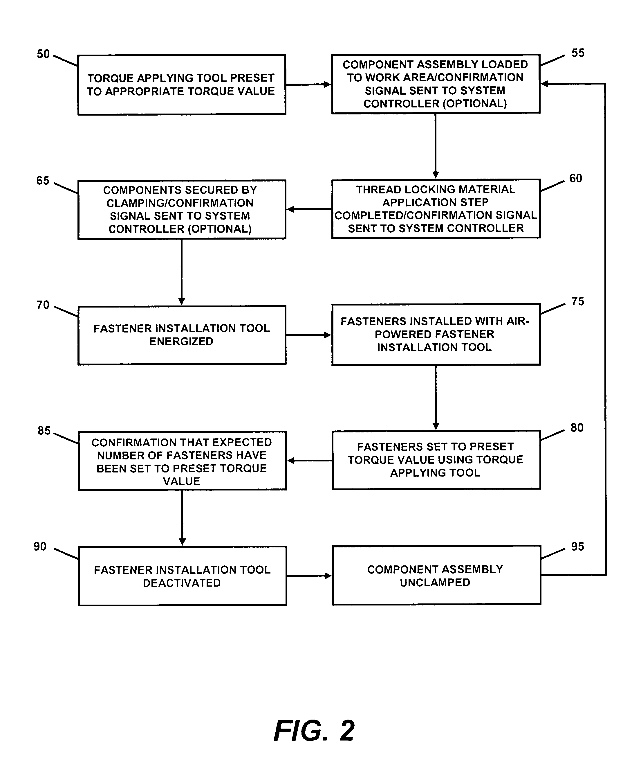
[0021]Exemplary embodiments of the system and method of the present invention can be observed in FIGS. 1–3. Each of the embodiments can be seen to utilize a system controller 5. The system controller 5 preferably includes a programmable microprocessor. The microprocessor may be provided in the form of a programmable logic controller (PLC), or a personal computer, for example. The system controller 5 is in communication with various sensors 10 that are used to create the interlocks preferred for proper process control. Sensors 10 may be provided to monitor a variety of process conditions / steps. In the process depicted by the block diagram of FIG. 2, for example, sensors are provided to indicate that the component assembly has been properly loaded into the work area, that a thread locking material application step has been completed, and that the component assembly has been adequately secured (clamped). In the block diagram of FIG. 3 a sensor is provided to determine when installatio...


PUM

PropertyMeasurementUnit
Poweraaaaaaaaaa
Torqueaaaaaaaaaa
Orderaaaaaaaaaa

Abstract

A system and method for guaranteeing that a torque application operation proceeds in a predetermined order. The system and method of the present invention can be used in processes that require the completion of one or more preparatory or post-torque application process steps. The steps of the overall process can be interlocked, so that the order of the process is controlled. Power to certain tool(s) used in the process may be withheld until certain process steps are accomplished, and said tool(s) may be automatically de-energized after the torquing operation is completed. Similarly, power to downstream tools may be withheld if the torquing operation is determined to be unsatisfactory or incomplete. A torque monitor / controller is provided to ensure that all elements requiring torquing are properly serviced, and that the amount of torque applied to each element is satisfactory.

Description

BACKGROUND AND SUMMARY OF THE INVENTION[0001]The present invention is directed to a torque guarantee system and, more particularly, to a torque guarantee system for use in a process requiring repeated torque application. For example, the torque guarantee system of the present invention may be employed in an assembly line process to guarantee that one or more fasteners of a particular component, or assembly of components, is consistently tightened with a preselected amount of torque.[0002]In many industrial and assembly-type operations, it is often critical that particular fasteners be installed with a predetermined amount of torque. The amount of torque used may be based on a number of factors including, for example, the material(s) through which the fastener(s) passes, the role of the fastener, the environment to which the fastened component(s) will be subjected, and the construction of the fastener itself. For example, if a fastener is overtightened, it may cause unnecessary and u...

Claims


Application Information

Patent Timeline
IPC IPC(8): B23Q15/00
CPCB25B23/14Y10T29/53039Y10T29/53
Inventor BARR, GARYTHOMAS, JAROM
Owner HONDA MOTOR CO LTD
Why Eureka
Try Eureka