Double disconnect assembly for multi-axle vehicles

a technology of drive assembly and auxiliary rear axle, which is applied in the direction of mechanical actuator clutches, mechanical equipment, transportation and packaging, etc., can solve the problems of auxiliary rear axle torque transmission also interrupting the clutch, etc., and achieves reduced travel distance, less wear, and greater fuel economy

Inactive Publication Date: 2006-08-29
DANA AUTOMOTIVE SYST GRP LLC
View PDF23 Cites 26 Cited by
  • Summary
  • Abstract
  • Description
  • Claims
  • Application Information

AI Technical Summary

Benefits of technology

[0009]The present invention provides a system whereby axles of a tandem or multi-axle vehicle may be easily and quickly engaged and disengaged as required. The present invention allows the ring gear and differential gears to remain stationary when the axle is disengaged.
[0010]In multi-axle vehicles, a dual disconnect mechanism is contained in the front and auxiliary rear axles. When only the primary rear axle is necessary to propel the vehicle (e.g., during highway use) the transfer case interrupts torque to the front axle. Similarly, a clutch also interrupts torque transmission to the auxiliary rear axle. In this mode, the dual disconnect mechanism prevents the axle output shafts from back-driving the differential, thereby reducing parasitic losses and wear.
[0014]Another aspect of the clutch mechanism of the invention provides a pair of split spline teeth on both the axle shaft and the side gear to reduce the travel distance required to engage / disengage the dual axle disconnect system.
[0015]The differential assembly of the present invention possesses several advantages, including greater fuel economy, less wear, and less noise compared to previously known disconnect mechanism in which only a single output shaft and its axle shaft are disengaged from driving engagement with a differential when two-wheel drive mode is selected. Advantages of the present invention compared to previously known dual disconnect differential assemblies include a more robust shaft / gear design without increased packaged size, fewer parts and greater compactness, which makes it possible to utilize the present dual disconnect drive mechanism on any size vehicle, including a sub-compact automobile.
[0016]Additionally, the provision of the clutch, that interrupts torque transmission to the auxiliary rear axle, prevents unnecessary rotation of the ring gear and differential at the auxiliary rear axle.

Problems solved by technology

Similarly, a clutch also interrupts torque transmission to the auxiliary rear axle.

Method used


Image

  • Double disconnect assembly for multi-axle vehicles
  • Double disconnect assembly for multi-axle vehicles
  • Double disconnect assembly for multi-axle vehicles

Examples


Embodiment Construction

[0023]This invention will now be described in detail with reference to the best mode and preferred embodiments thereof.

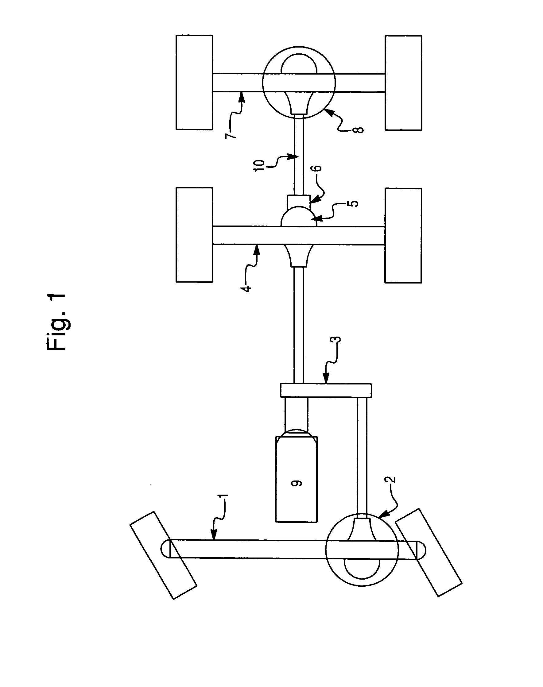
[0024]FIG. 1 is a schematic representation of the drive system for a tandem or multi-axle vehicle including a front steerable axle 1 with a first drive axle front differential 2, a torque transfer case 3, a primary rear axle 4 with associated differential 5, a rear clutch 6, and a second drive axle auxiliary rear axle 7 with associated rear differential 8. The transfer case 3 selectively transfers torque from the engine / transmission 9 to the front and rear axles 1, 4, 7.

[0025]The rear clutch 6 disconnects the rear prop shaft drive train 10 from the rear axle 4 and rear differential 5. However, absent any other disconnect mechanism the prop shaft 10, auxiliary rear axle 7, and auxiliary rear differential 8 continue to rotate due to back-driving caused by the auxiliary rear wheels drivingly connected to the auxiliary rear axle 7.

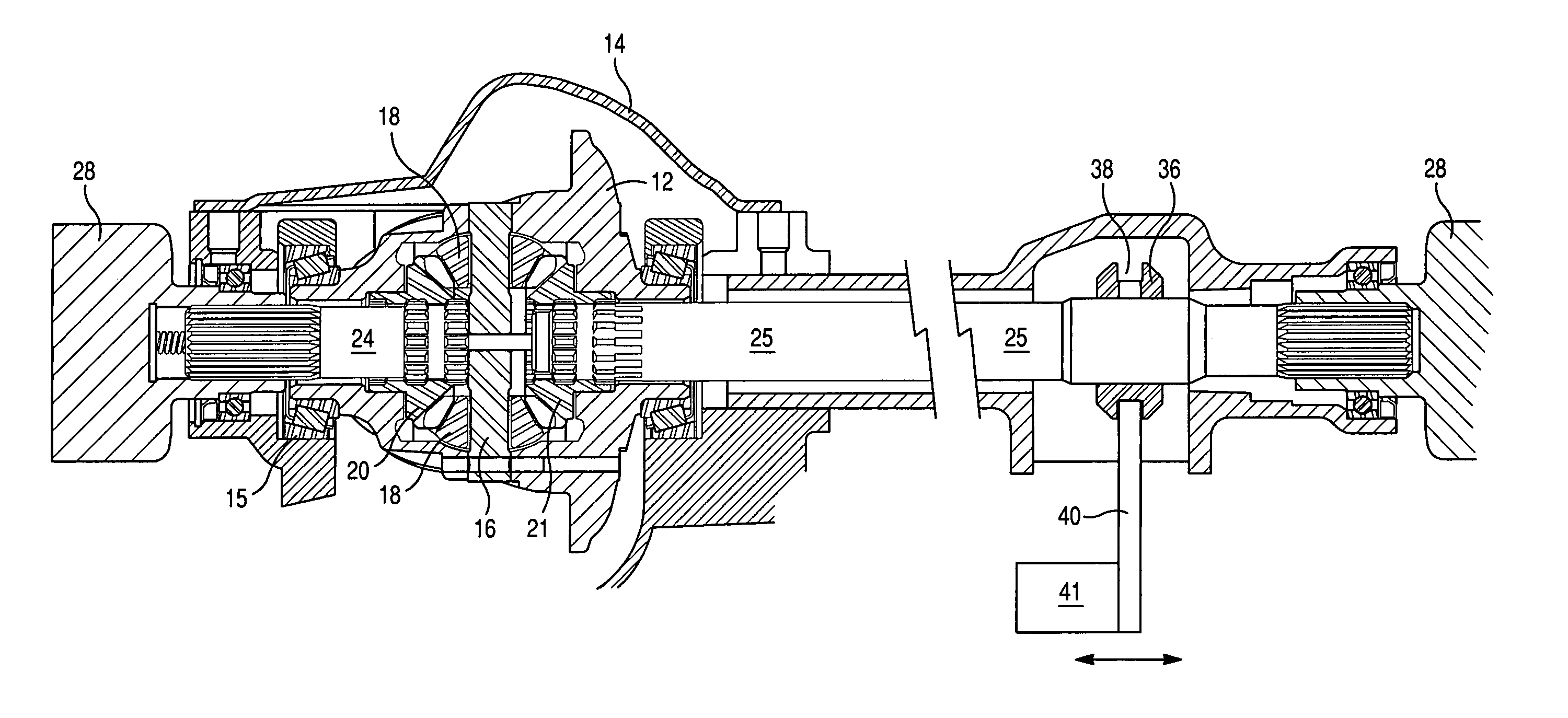
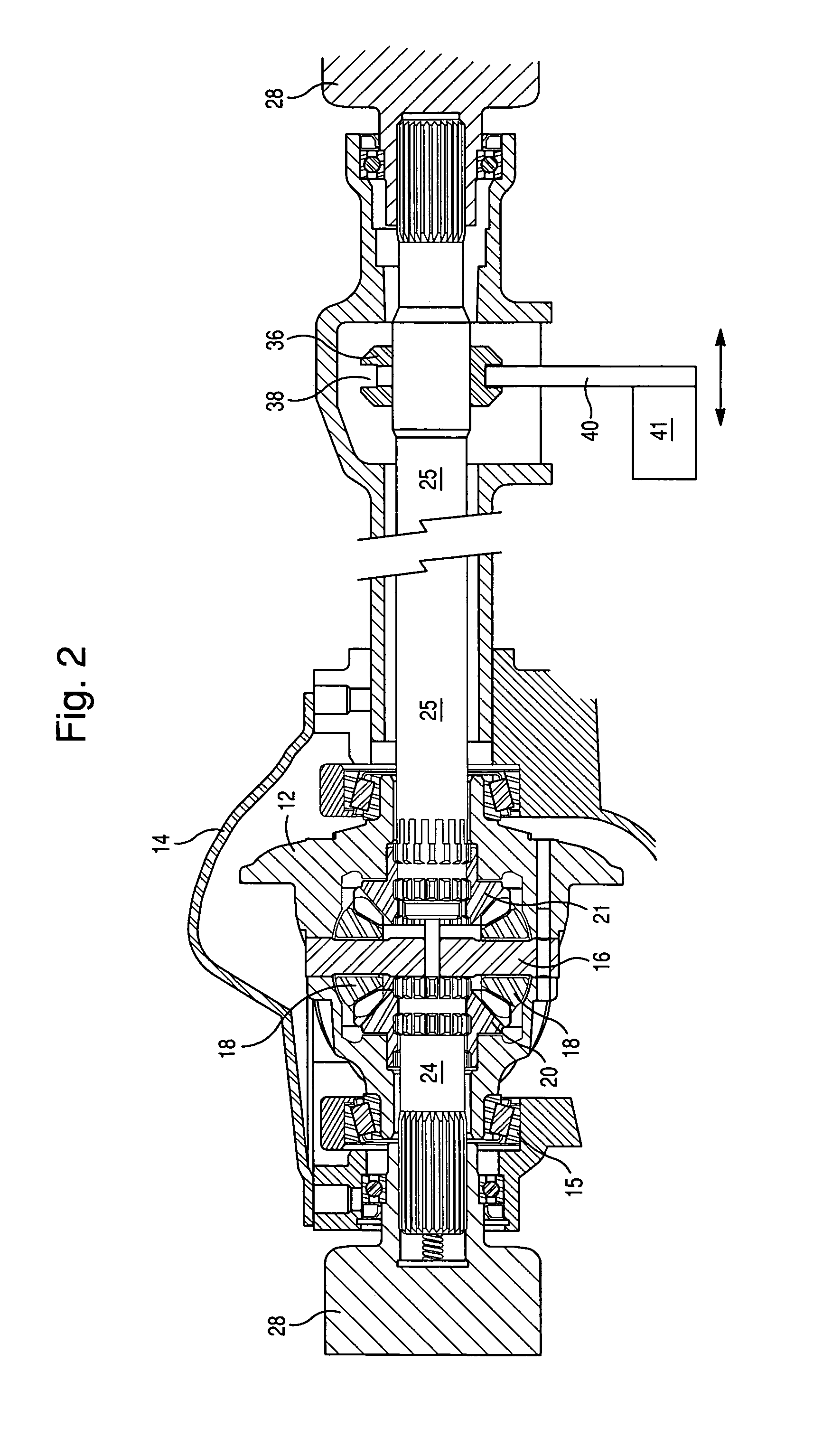
[0026]Referring now to FIG. 2, a dual d...


PUM


Abstract

An axle disconnect system is provided whereby axles of a tandem or multi-axle vehicle may be easily and quickly engaged and disengaged as required and whereby the ring gear and differential gears remain stationary when the axle is disengaged. In multi-axle vehicles, a dual disconnect mechanism is contained in the front and auxiliary rear axles. When only the primary rear axle is necessary to propel the vehicle (e.g., during highway use) the transfer case interrupts torque to the front axle. Similarly, a clutch also interrupts torque transmission to the auxiliary rear axle. In this mode, the dual disconnect mechanism prevents the axle output shafts from back-driving the differential, thereby reducing parasitic losses and wear.

Description

BACKGROUND OF THE INVENTION[0001]1. Field of the Invention[0002]This invention relates to differential disconnect drive assemblies or mechanisms, and in particular to dual disconnect drive assemblies, for tandem and multi-axle vehicles which can be quickly and easily engaged and disengaged as required.[0003]2. Description of Related Art[0004]Four-wheel drive vehicles, which are operable in either a two-wheel drive mode or a four-wheel drive mode, have gained widespread popularity. Axle disconnect mechanisms, or differential disconnect mechanisms or assemblies for such vehicles are known.[0005]Commonly used disconnect mechanisms for four-wheel drive vehicles disconnect only one of the two output shafts on an axle assembly which is driven part time. This causes the pinion gears and the side gears of the differential to rotate due to back driving, although the differential case remains stationary. This is not compatible with speed-sensitive limited slip differentials. Also, single axle...

Claims


Application Information

Patent Timeline
Patent Type & Authority Patents(United States)
IPC IPC(8): B60K23/08B62D61/10F16D13/54
CPCB60K23/08
Inventor BORGEN, WAYNE LEEHUNT, WILLIAM GORDONYOSHIOKA, JUN
Owner DANA AUTOMOTIVE SYST GRP LLC
Why Eureka
Try Eureka