Interface for interfacing an imaging engine to an optical code reader

a technology of code reader and interface, which is applied in the direction of printers, cameras, instruments, etc., can solve the problems that each of these proposed solutions yielded limited success, and achieve the effect of improving the imaging engine, increasing the working range, and reducing the risk of scanner damag

Inactive Publication Date: 2006-08-29
SYMBOL TECH INC
View PDF43 Cites 82 Cited by
  • Summary
  • Abstract
  • Description
  • Claims
  • Application Information

AI Technical Summary

Benefits of technology

[0014]In accordance with the present invention, an optical code reader system having an improved imaging engine is provided. The optical code reader system includes an imaging engine which is configured to achieve an 85 micron, sub 20 milli-second, two position focus of an optical imaging system for the purpose of increasing working range without compromising scanning aggressiveness in a Proton sized barcode scan engine.

Problems solved by technology

Each of these proposed solutions yielded limited success.

Method used


Image

  • Interface for interfacing an imaging engine to an optical code reader
  • Interface for interfacing an imaging engine to an optical code reader
  • Interface for interfacing an imaging engine to an optical code reader

Examples


Embodiment Construction

[0037]Reference is now made in specific detail to the drawings in which like reference numerals identify similar or identical elements throughout the several views.

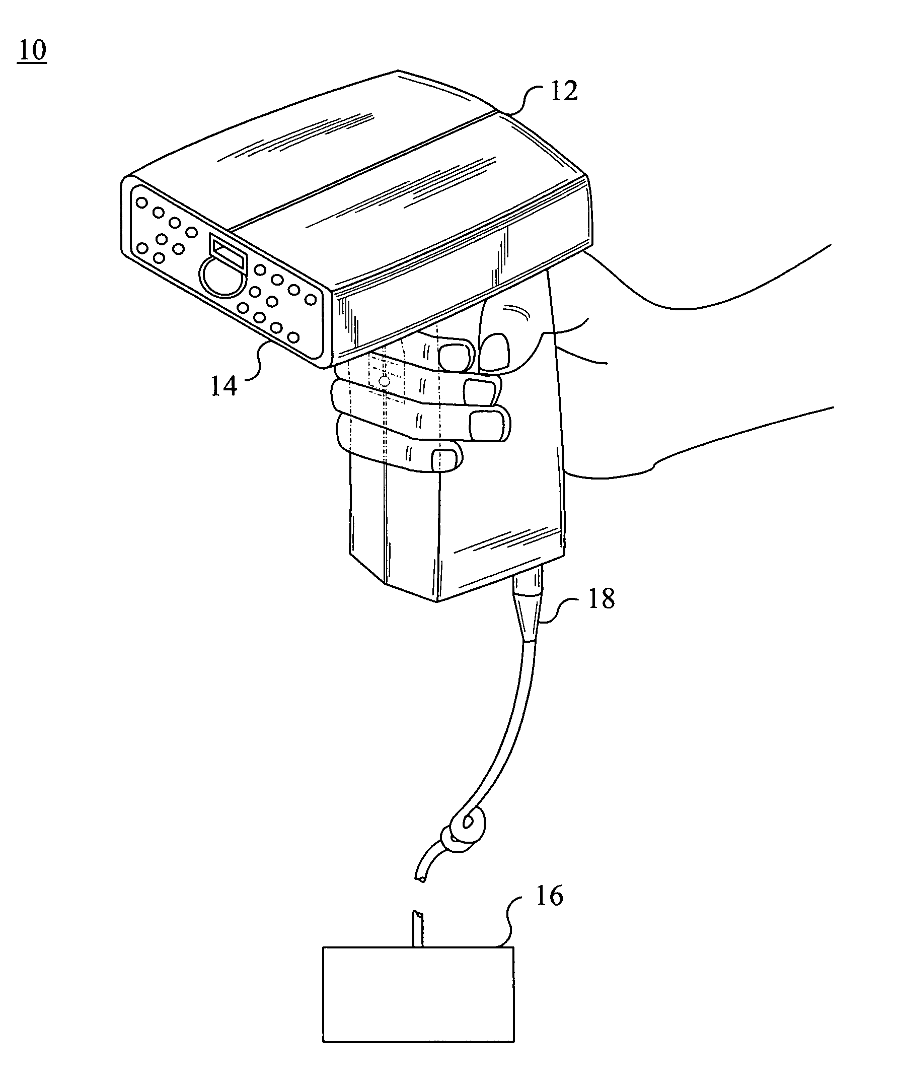
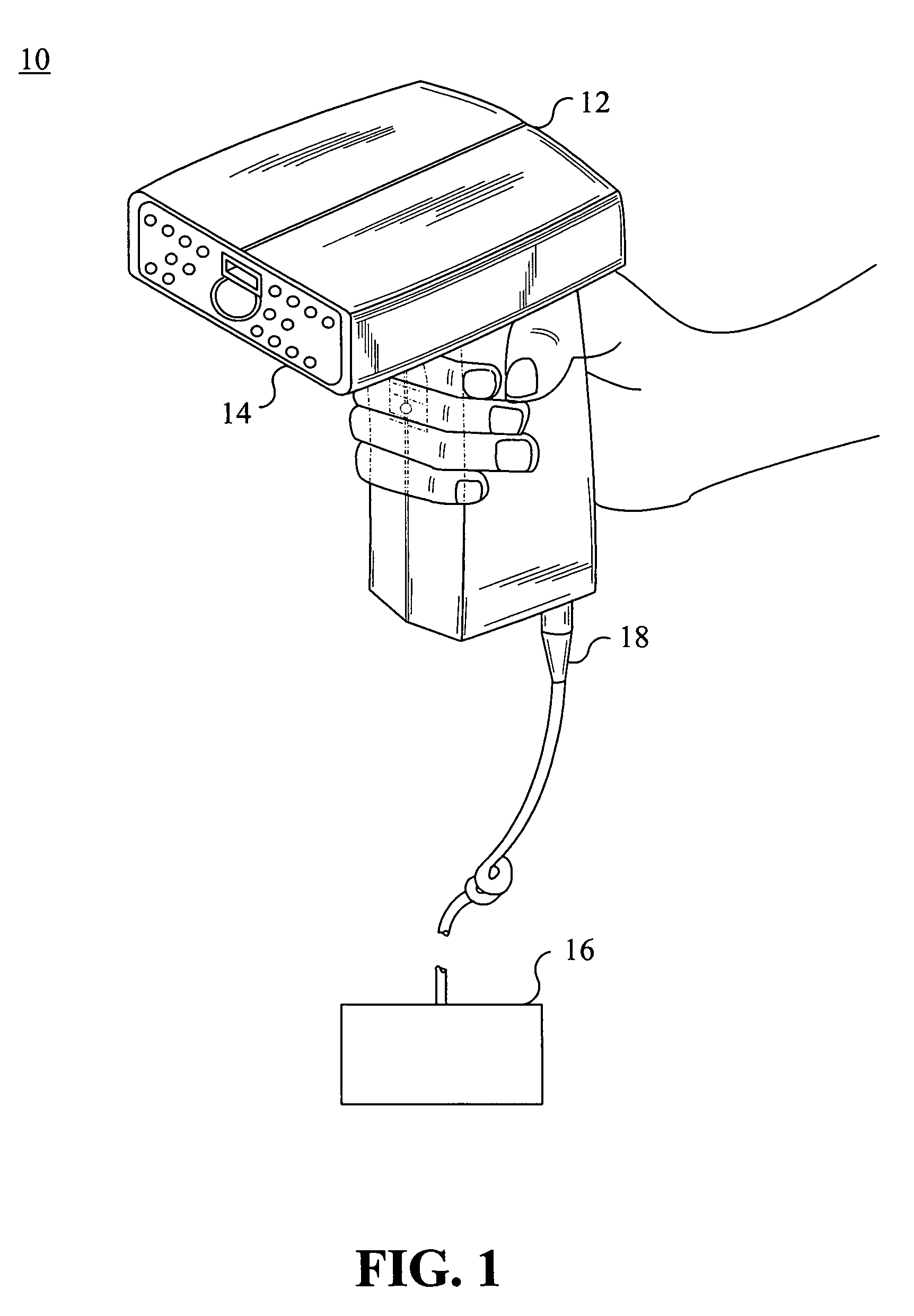
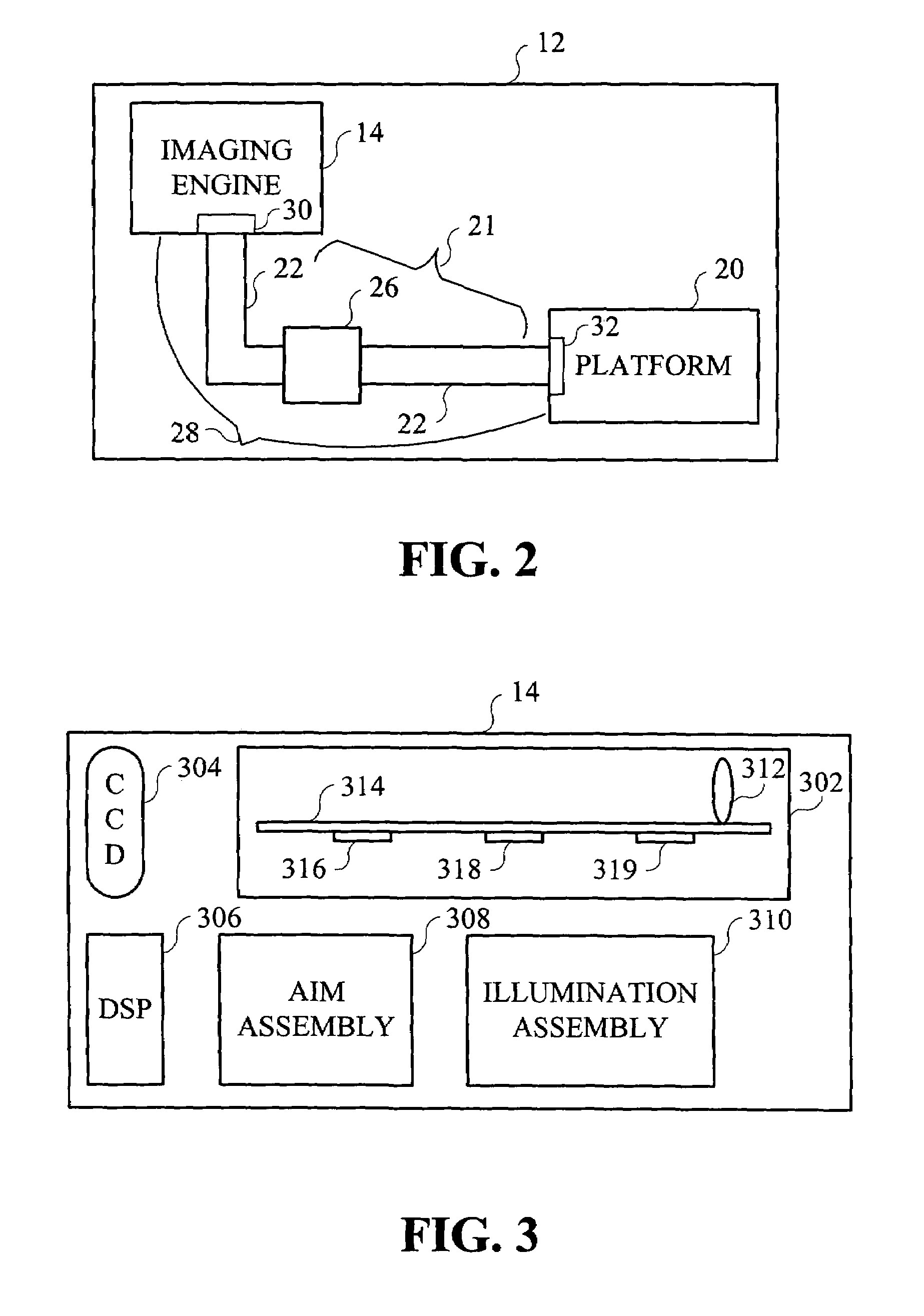
[0038]FIG. 1 shows an optical code reader system 10 including an optical code reader 12 having an imaging engine 14, where the optical code reader 12 is preferably connected to a host terminal 16 via a cable 18. FIG. 2 shows a block diagram of the optical code reader 12, in which the imaging engine 14 is interfaced to a platform 20. Transmission assembly 21 is provided including at least one connector 22 and / or at least one transmission adaptation device 26 having individually or collectively electrical / and or data transmission circuitry for providing electrical and / or data communication between the imaging engine 14 and the platform 20.

[0039]An interface assembly 28, for providing data and / or electrical communication between the imaging engine 14 and the platform 20, includes an input / output (I / O) means 30, such as an I / ...


PUM


Abstract

An optical code reader having means for focusing an imaging optics assembly on a target image. The optical code reader includes a chassis and an imaging optics assembly pivotally mounted on the chassis. The imaging optics assembly is housed within an opto-mechanical barrel assembly. Pivotal movement of the opto-mechanical barrel assembly adjusts the focus of the imaging optics assembly on a target image. The optical code reader further includes an illumination device and an aiming device.

Description

PRIORITY[0001]This application is a continuation-in-part application of co-pending U.S. patent application Ser. No. 10 / 459,935, filed on Jun. 12, 2003, which claims priority to two U.S. Provisional Applications filed on Feb. 13, 2003 and Apr. 4, 2003 and assigned U.S. Provisional Application Ser. Nos. 60 / 447,093 and 60 / 460,370, respectively, the contents of which are incorporated by reference herein.BACKGROUND OF THE INVENTION[0002]1. Field of the Invention[0003]This invention relates to imaging in optical code reading devices. Aspects of the invention are particularly useful in solid state, area image sensor based, handheld code readers which are positioned at variable orientations and distances with respect to a target code.[0004]2. Description of the Related Art[0005]Optical codes are patterns made up of image areas having different light reflective or light emissive properties, which are typically assembled in accordance with a priori rules. The term “barcode” is typically used ...

Claims


Application Information

Patent Timeline
Patent Type & Authority Patents(United States)
IPC IPC(8): G06K7/10G02B7/04G02B27/20
CPCG02B7/04G06K7/10811G06K7/10722G02B27/20
Inventor KOGAN, EDUARDGIORDANO, JOSEPHSHAMKOVICH, ANDREIZHANG, HENG
Owner SYMBOL TECH INC
Why Eureka
Try Eureka