Connector for apparatus

Inactive Publication Date: 2006-08-29
AUTONETWORKS TECH LTD +2
View PDF4 Cites 39 Cited by
  • Summary
  • Abstract
  • Description
  • Claims
  • Application Information

AI Technical Summary

Benefits of technology

[0013]Since an extension portion in the form of extending from the female connecting portion to the opposite side of the wire side terminal is provided in the apparatus side terminal, a seal member externally fitted around the extension portion seals a gap between the apparatus side terminal and the inner circumference of the apparatus side housing, it is possible to securely seal the gap between the apparatus side terminal and the apparatus side housing, even in the case where the apparatus side terminal is not connected to the electric wire and has the female connecting portion.
[0014]Since the extension portion is regulated from displacement in the radial direction by the spacer, it is possible to keep the deformation amount of the seal member externally fitted around the extension portion even in the circumferential direction, exhib

Problems solved by technology

However, in the conventional connector for apparatus, when connecting or disconnecting the wire to or from the apparatus, a troublesome operation of fastening or releasing the bolt, and an operation of mounting or dismounting the cover on or from the terminal base are required, resulting in worse operability when connecting or disconnecting the wire for the maintenance.
By the way, when the apparatus side terminal is pr

Method used


Image

  • Connector for apparatus
  • Connector for apparatus
  • Connector for apparatus

Examples


embodiment 1

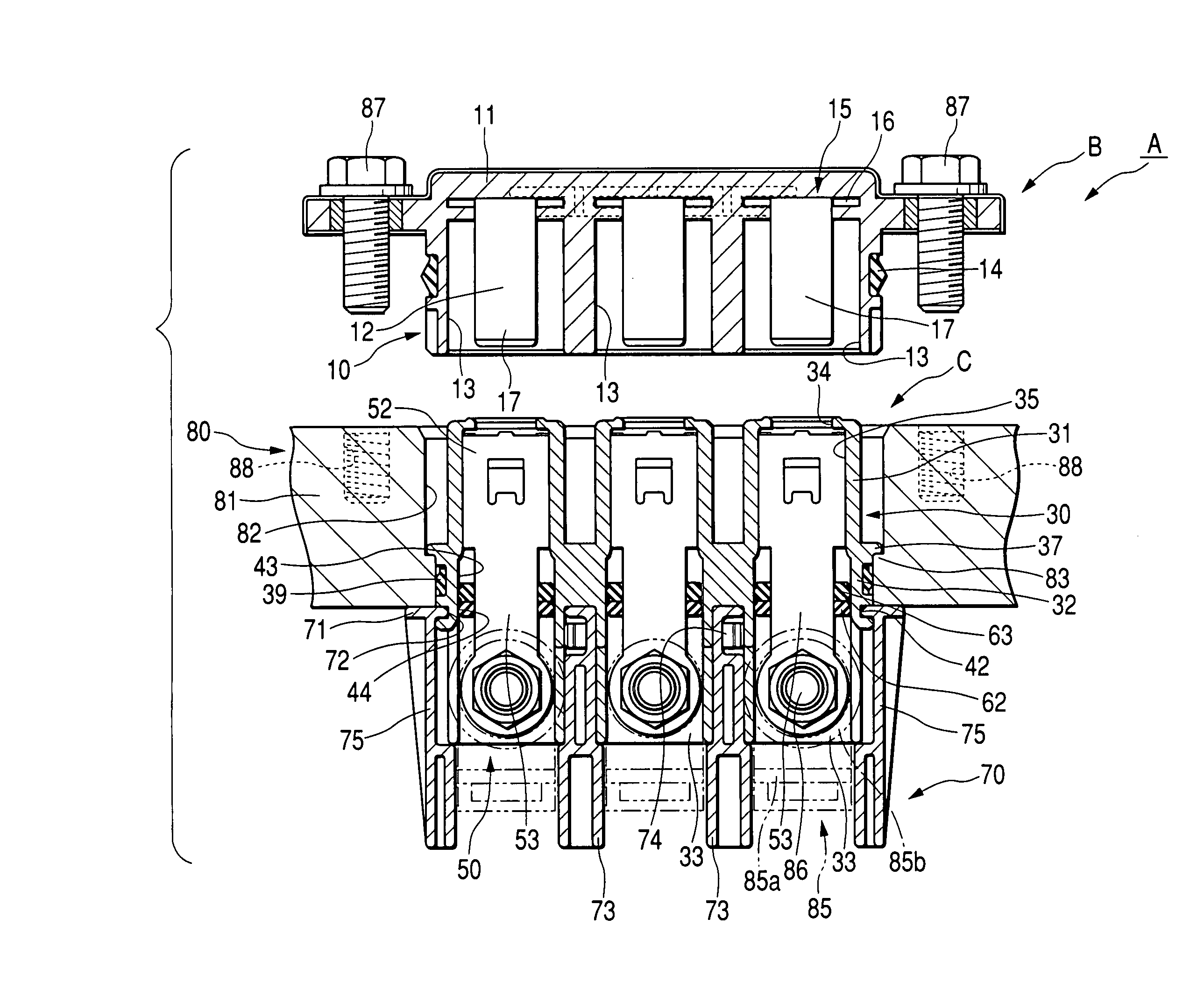
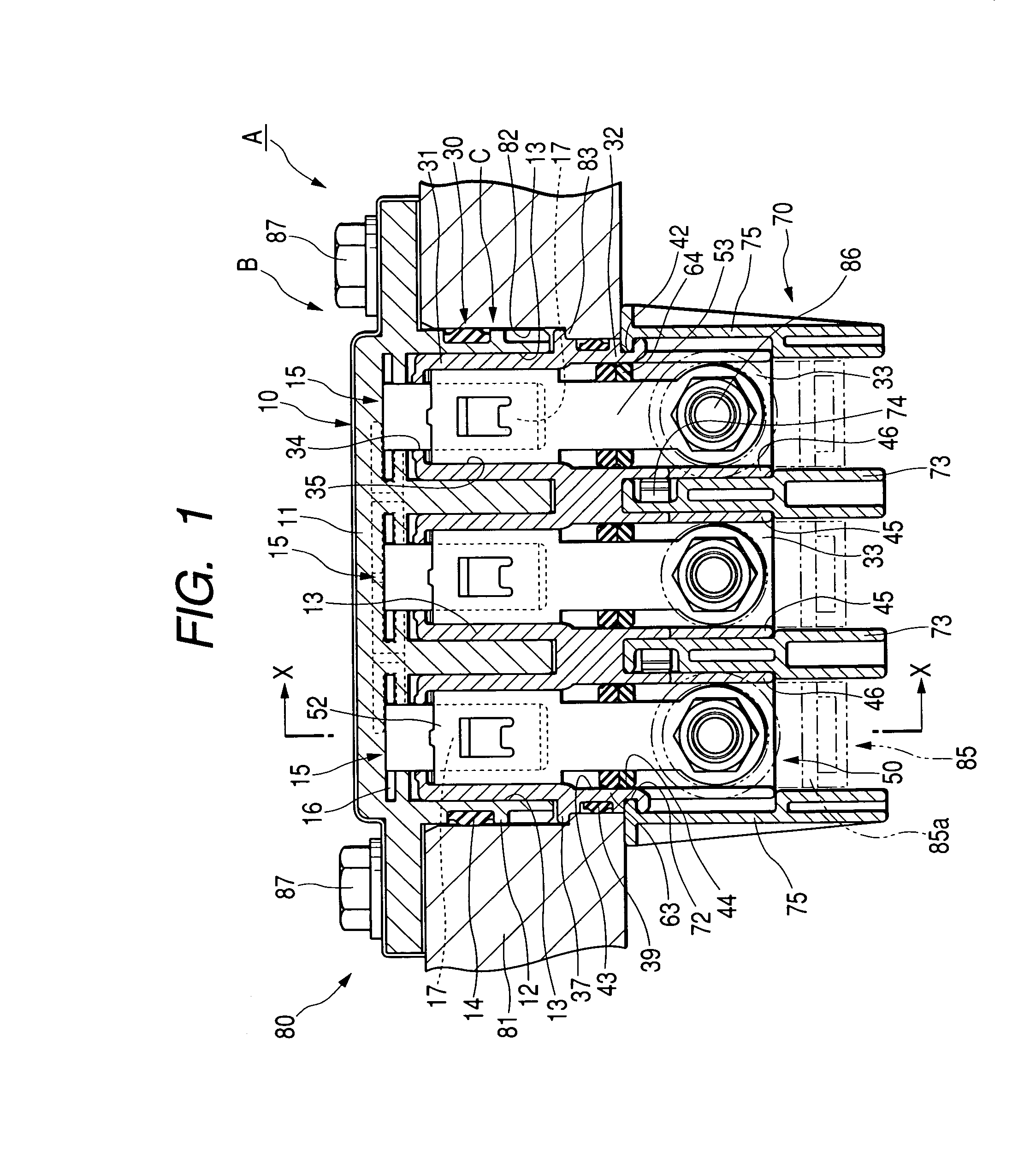
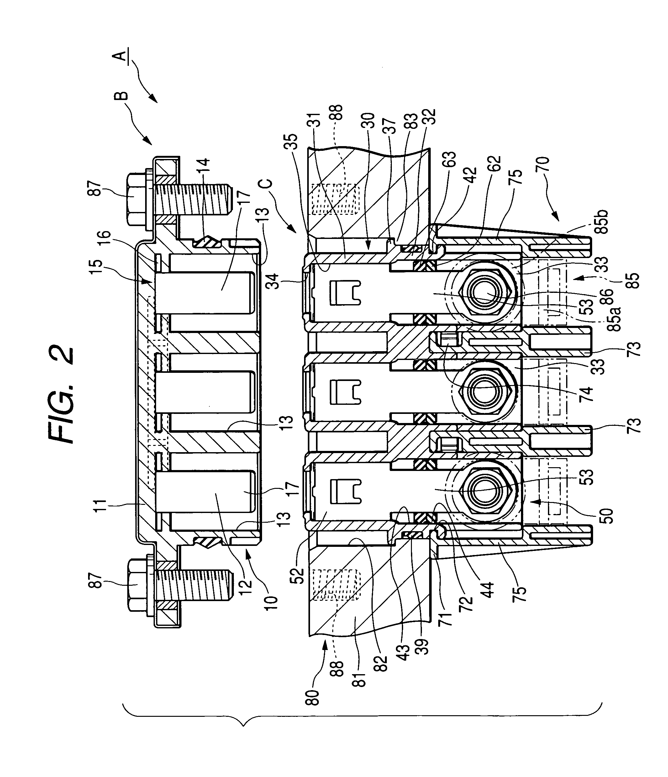
[0036]Referring to FIGS. 1 to 18, an embodiment 1 of the present invention will be described below.

[0037]First of all, an apparatus 80 in which an connector for apparatus A of this embodiment is mounted will be described below. The apparatus 80 (e.g., a motor for electric automobile, an inverter) has an apparatus main body (e.g., motor stator), not shown, that is contained within a shield case 81. On an upper face of the shield case 81, amounting hole 82 to penetrate vertically through the outside and the inside of the shield case 81 is formed. The mounting hole 82 has an oblong shape extending crosswise. A stopper 83 having a similar shape (i.e., oblong) to that of the mounting hole 82 and having a diameter of a size smaller than the mounting hole 82 is formed over the entire circumference and continuously at the lower end portion on the inner circumference of the mounting hole. Within the shield case 81, three apparatus direct coupling terminals 85 directly coupled with the appara...

embodiment 2

[0067]Referring to FIG. 19, an embodiment 2 of the invention will be described below.

[0068]The embodiment 2 is different from the embodiment 1, in that a spacer 90 and a seal member 91 are attached to the extension portion 53. The other constitution is the same as that of the embodiment 1. The same parts are designated by the same numerals, and the description of the structure, action and effect is omitted.

[0069]In the embodiment 1, the spacer 62 and the seal member 63 are directly fitted around the extension portion 53, while in the embodiment 2, the spacer 90 alone is directly fitted around the extension portion 53 but the seal member 91 is like a ring to be fitted into a seal groove 92 formed around the circumference of the spacer 90 and attached around the spacer 90. In this embodiment 2, the spacer 90 after molding is fixed to the extension portion 53, but may be molded integrally with the extension portion 53. Likewise, the seal member 91 may be molded integrally with the oute...


PUM


Abstract

In a connector for apparatus, an extension portion extends from a female connecting portion to an opposite side of a wire side terminal. A gap between the apparatus side terminal and an inner circumference of the apparatus side housing is sealed with a seal member which is externally fitted around the extension portion of the apparatus side terminal.

Description

FIELD OF THE INVENTION[0001]The present invention relates to an connector for apparatus.DESCRIPTION OF THE RELATED ART[0002]Some of the connector for apparatus for connecting the electric wire to an apparatus such as a motor for an electric automobile have a structure in which a terminal part of the electric wire is held with a housing, which is secured to a case of the apparatus, and the wire is passed through a mounting hole of the case to connect a wire side terminal fixed to the terminal part of the wire to an apparatus side terminal within the case.[0003]Though the connection between terminals is bolted, to allow for this bolting operation, the case is provided with a terminal base for exposing the apparatus side terminal out of the case, and after the bolting operation, a cover is placed over the terminal base to hide a connecting portion of the terminal (e.g., refer to JP-A-2002-125348).[0004]However, in the conventional connector for apparatus, when connecting or disconnecti...

Claims


Application Information

Patent Timeline
IPC IPC(8): H01R13/73H02B1/01H01R13/52H01R4/46H01R13/512H02K5/22
CPCH01R13/512H01R4/46
Inventor MIYAZAKI, SHO
Owner AUTONETWORKS TECH LTD
Why Eureka
Try Eureka