Safety jump training apparatus

a safety and jump technology, applied in the field of jump training equipment, can solve the problems of creating potential hazards for users, injury to athletes or coaches, and prior art jump trainers that have not integrated adequate safety features so as to minimize the risk of an athlete being injured and provide the height adjustment of the jump measurement device

Active Publication Date: 2006-08-29
SPORTS IMPORTS
View PDF14 Cites 21 Cited by
  • Summary
  • Abstract
  • Description
  • Claims
  • Application Information

AI Technical Summary

Benefits of technology

[0009]The safety jump training apparatus of the present invention is one designed for safely mounting on a wall and permits an athlete to safely measure their vertical leap. The apparatus has two positions; an operating position and a storage position. When the apparatus is in the operating position it is substantially orthogonal to the mounting wall and provides the athlete exceptional access to the apparatus. Conversely, the apparatus is substantially parallel to the wall when in the storage position, thereby removing the apparatus from areas subject to walking traffic, or other athletic events, and minimizing the risk of inadvertent contact.
[0010]The safety jump training apparatus includes a jump measurement device and a rotating support to attach the measurement device to a mounting plate, as well as numerous safety features. Briefly, the safety features include cooperating locking pin recesses and a locking pin to secure the apparatus in either the operating position or the storage position, a lock to adjustably secure the vertical height of the measurement device, a translation resistor to control the movement of the measurement device when the lock is disengaged, a safety position limiter to ensure that the measurement device is always a predetermined distance above the ground, and a safety cover to safely contain majority of the apparatus.
[0012]The rotating support has at least one arm and a vertical sleeve attached to the at least one arm. The vertical sleeve is shaped to cooperate with the shape of the vertical post so that the vertical post is slidably received by the sleeve, thereby allowing adjustment of the height of the jump measuring device. The motion of the vertical post in the sleeve is limited by the safety position limiter such that the end of the vertical post is limited to a predetermined dimension above a floor surface to ensure that the end does not injure a foot of the athlete during adjustment of the post.
[0013]The lock is attached to the sleeve and serves to provide the adjustability of the height of the jump measurement device. The lock has an engaged position, wherein the vertical post is secured within the sleeve, and a disengaged position, wherein the vertical post is not secured by the lock. The automatic translation resistor is yet another safety improvement designed to minimize the risk of an athlete either getting their finger pinched in the apparatus or their foot injured by an uncontrolled post. The automatic translation resistor is attached to the sleeve and continuously applies a compressive force on the vertical post to counteract the gravitational force on the jump measurement device and prevent it from accidental translation within the sleeve when the lock is disengaged. The automatic translation resistor requires the athlete to disengage the lock and intentionally apply force to the vertical post in order to adjust the height of the jump measurement device.
[0014]The at least one rotational mount is attached to the mounting plate and is designed to releasably and rotationally attach the arm to the mounting plate. The at least one rotational mount permits the rotating support and the jump measurement device to rotate from the operating position to the storage position where the rotating support and jump measurement device are substantially parallel to the wall. The at least one rotational mount includes a guide plate having a plate guide pin recess that aligns with an arm guide pin recess formed in the arm such that a guide pin is received by the plate guide pin recess and the arm guide pin recess thereby releasably and rotably joining the guide plate and the at least one arm. The guide plate may include at least one auxiliary recess arranged such that a padlock may be secured through the auxiliary recess thereby preventing unauthorized users from rotating the jump measuring device from the storage position to the operating position.

Problems solved by technology

Prior art jump trainers have failed to incorporate adequate safety features to minimize the risk of an athlete being injured while measuring vertical leap.
A common problem with early jump trainers, such as the one of U.S. Pat. No. 4,208,050 was that they were prone to tip over and cause injury to the athlete or coach.
Additionally, the barbell plates are often left scattered around the area of the trainer creating potential hazards for the users.
After all, if an athlete measuring their vertical leap lands with a portion of a foot on a plate, even if the plate is only one-quarter to one-half inch thick, the athlete often ends up with a severely sprained, or broken, ankle.
These steel posts create a potentially life threatening hazard to an athlete that has lost their balance and is falling in the vicinity of the posts.
Yet another problem with conventional jump trainers is that they consume a great deal of floor space and are not easily stored.
Such jump trainers are a dangerous hazard to a player chasing a ball out of bounds.
For instance, the wall-mounted jump trainer of U.S. Pat. No. 5,031,903 addresses the safety issues surrounding the base of floor mounted units, but presents other safety issues and drawbacks.
Rigidly attached jump trainers that extend orthogonally from the wall pose just as great a danger, if not greater, to athletes than ground mounted units.
In such installations the bottom of the jump trainer is at the head height of many athletes and creates an even greater danger than the floor mounted units, because it is rigidly attached to the wall.
Therefore, one can imagine that if such wall-mounted trainers were located around the perimeter of a gymnasium, an athlete chasing a loose ball could accidentally strike the device and knock themselves unconscious.

Method used


Image

  • Safety jump training apparatus
  • Safety jump training apparatus
  • Safety jump training apparatus

Examples


Embodiment Construction

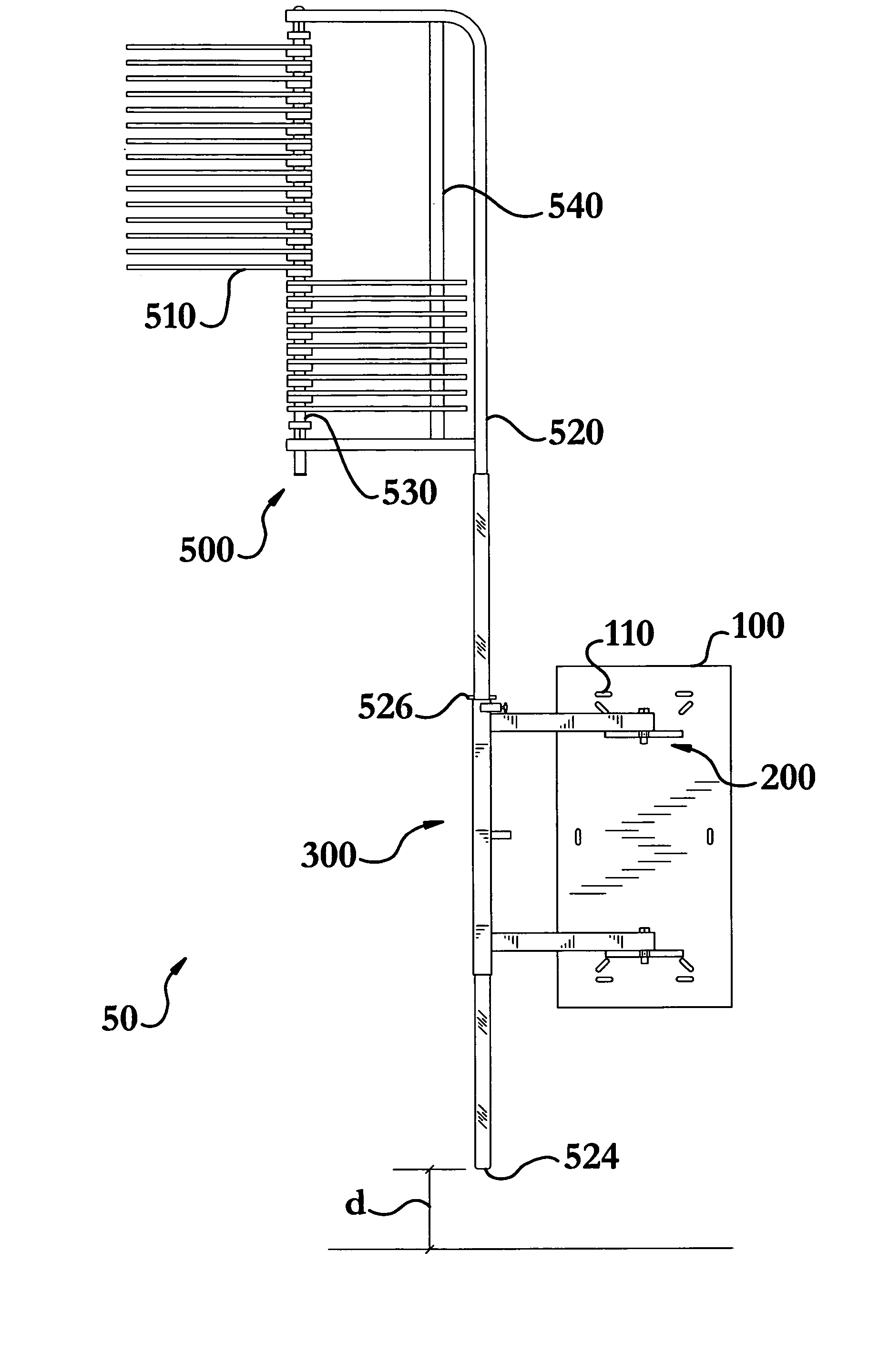
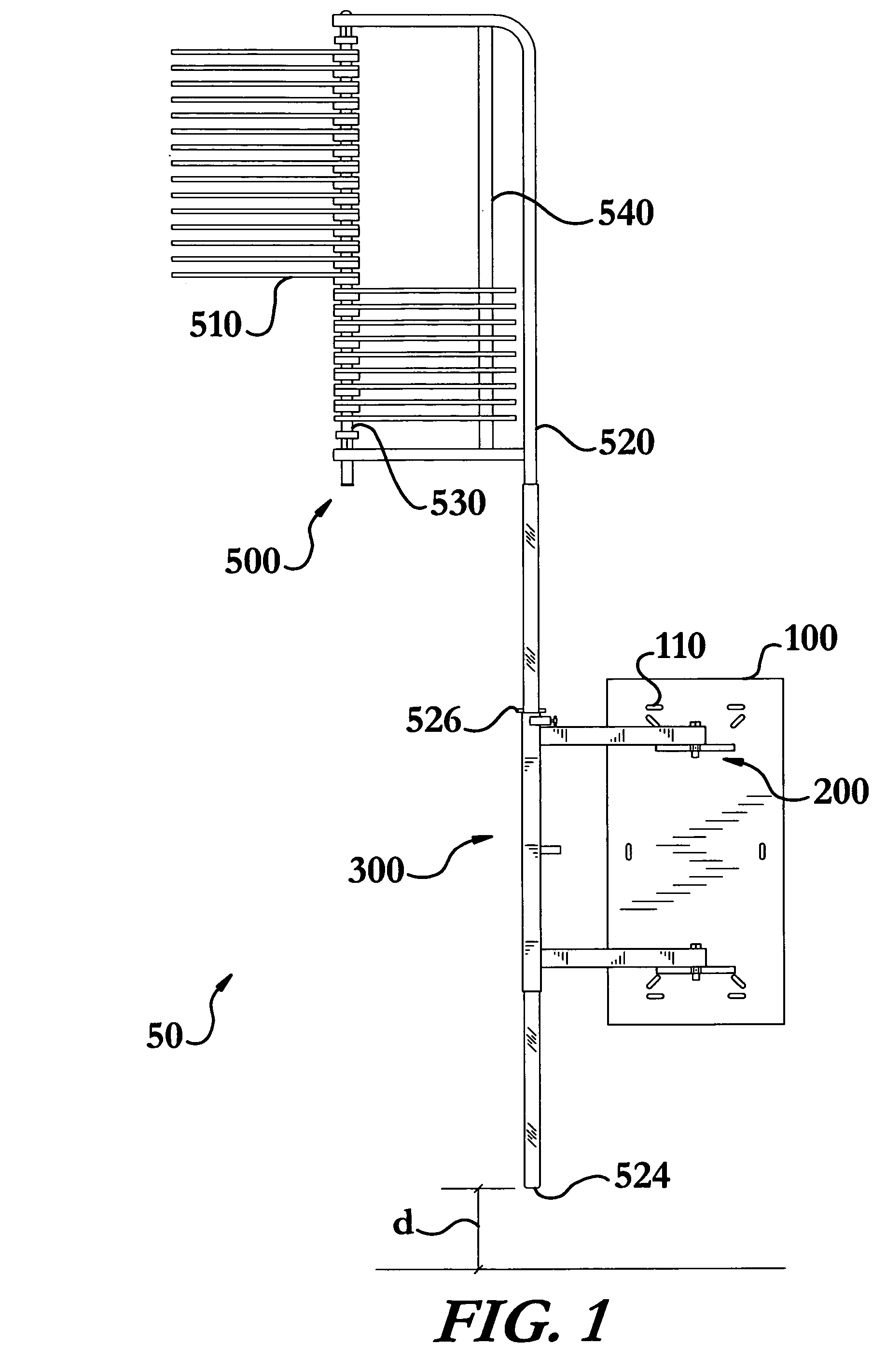
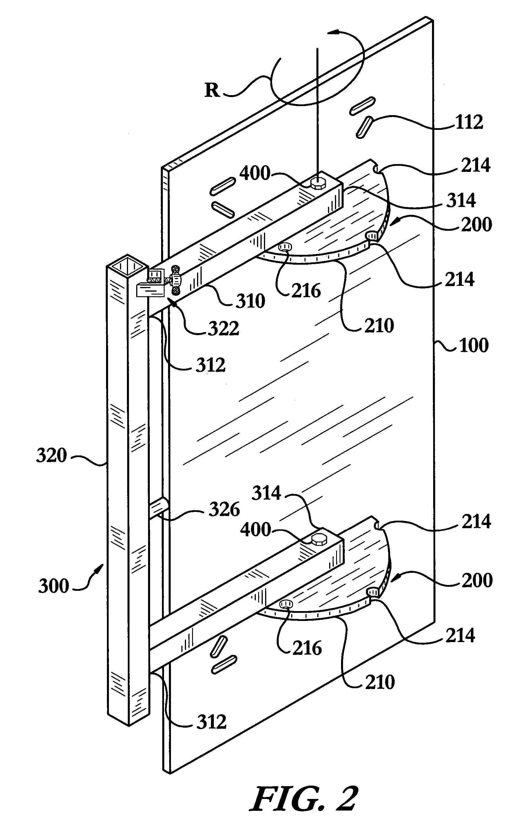
[0028]The safety jump training apparatus of the instant invention enables a significant advance in the state of the art. The preferred embodiments of the apparatus accomplish this by new and novel arrangements of elements and methods that are configured in unique and novel ways and which demonstrate previously unavailable but preferred and desirable capabilities.

[0029]The detailed description set forth below in connection with the drawings is intended merely as a description of the presently preferred embodiments of the invention, and is not intended to represent the only form in which the present invention may be constructed or utilized. The description sets forth the designs, functions, means, and methods of implementing the invention in connection with the illustrated embodiments. It is to be understood, however, that the same or equivalent functions and features may be accomplished by different embodiments that are also intended to be encompassed within the spirit and scope of t...


PUM


Abstract

A safety jump training apparatus designed for safely mounting on a wall to permit an athlete to safely measure their vertical leap. The safety jump training apparatus includes a jump measurement device and a rotating support to rotably attach the measurement device to a mounting plate, as well as numerous safety features. The safety features include cooperating locking pin recesses and a locking pin to secure the apparatus in either an operating position or a storage position, a lock to adjustably secure the vertical height of the measurement device, a translation resistor to control the movement of the measurement device when the lock is disengaged, a safety position limiter to ensure that the measurement device is always a predetermined distance above the ground, and a safety cover to safely contain majority of the apparatus.

Description

TECHNICAL FIELD[0001]The present invention relates to the field of jump training devices, in particular, to a safety jump training device for safely measuring an athlete's vertical leap when in an operating position and having a storage position wherein the device is safely and compactly stored against a wall.BACKGROUND OF THE INVENTION[0002]In the past quarter-century athletes and coaches have come to realize that the vertical leap of an athlete is a good indicator of success in a wide variety of sports. As such, today an athlete's vertical leap is used to measure an athlete's capabilities in much the same way the 40 yard dash is used. With this recognition of the importance of the vertical leap, athletes now train to improve their vertical leap. Accordingly, devices that safely and accurately measure an athlete's vertical leap are in demand.[0003]Prior art jump trainers have failed to incorporate adequate safety features to minimize the risk of an athlete being injured while measu...

Claims


Application Information

Patent Timeline
Patent Type & Authority Patents(United States)
IPC IPC(8): A63B5/16A63B69/00A61H3/00A63B5/00A63B67/10
CPCA63B5/00A63B5/16A63B67/10
Inventor UNDERWOOD, BRADFORD JDUNLAP, LEGAL REPRESENTATIVE, CYNDIE M.DUNLAP, DECEASED, DAVID K
Owner SPORTS IMPORTS
Why Eureka
Try Eureka