
Combinatorial synthesis system

a combinatorial synthesis and chemical reaction technology, applied in sequential/parallax process reactions, fluid speed measurement, burettes/pipettes, etc., can solve the problems of increasing the procedure, affecting the affecting the reaction efficiency of the reaction,

Inactive Publication Date: 2006-08-29
CALIFORNIA INST OF TECH
View PDF80 Cites 174 Cited by
  • Summary
  • Abstract
  • Description
  • Claims
  • Application Information

AI Technical Summary

Benefits of technology

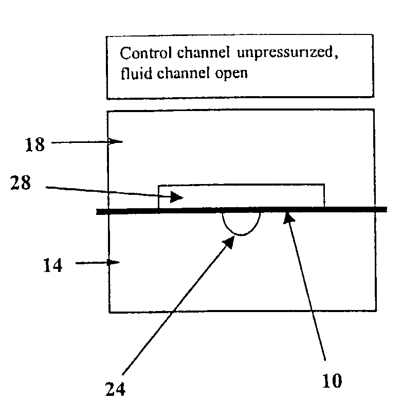
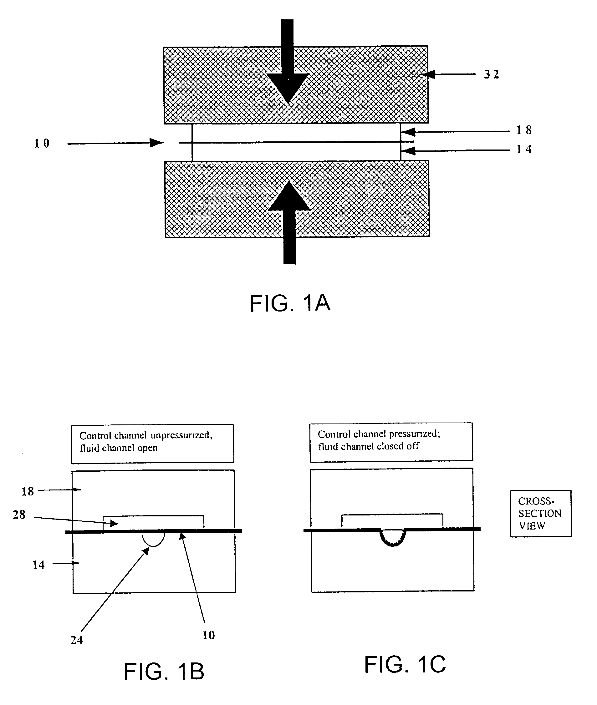
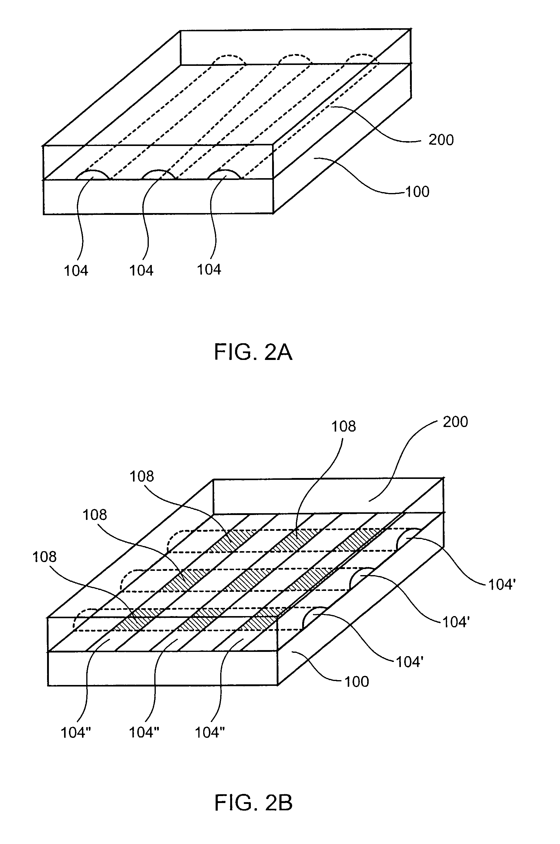
[0017]Still in another embodiment, at least a portion of the control channels are aligned in between the fluid flow channels. In addition, at least a portion of the control channels is aligned on top of the fluid flow channels. In this manner, actuation of the control channel controls the fluid flow within the fluid flow channels that are positioned directly below the control channels.

Problems solved by technology

This method requires specialized reagents (e.g., photoremovable protecting groups), which is relatively expensive and presently have significantly lower coupling yield than conventional reagents.
This photolithographic method also typically requires 4N masks, thereby adding a considerable expense to the procedure.
Furthermore, any decreased deprotection efficiency results in the decreased coupling efficiency.
Conventional reagents do not suffer this problem because it is the coupling step which is most inefficient, and missed couplings can be terminated (nearly completely) with the capping step.
While this technique uses relatively inexpensive conventional chemical reagents with typically high coupling yield, it can deliver one, and only one, drop of reagents at a time, unless multiple jets are used simultaneously.
Furthermore, two drops of liquid applied too closely together on a surface tend to spread into each other and mix, thereby limiting the array density achievable with the ink-jet method.
However, each method has its own limitations such as limited array density, increased production cost per array, and / or serial (i.e., non-parallel) synthesis.

Method used


Image

  • Combinatorial synthesis system
  • Combinatorial synthesis system
  • Combinatorial synthesis system

Examples


example 1

[0111]This example illustrates a process for synthesizing an array of all possible DNA 6-mers using a chemical apparatus of the present invention which has one elastomer member. It should be appreciated that the “elastomeric layer” of such an apparatus need not be an elastomer, provided one can obtain a good seal with the solid support either by temporary adhesion or by applying pressure.

[0112]The solid support is etched with the pattern shown in FIG. 8 for alignment purposes. There are four alignment marks near the corners. These marks line up with the corresponding alignment marks on patterns shown in FIGS. 9, 10, and 11. The two short diagonal lines in the upper left hand corner are “orientation marks.”

[0113]FIGS. 9, 10, and 11 are the patterns that are used to make the molds for elastomer layers. Thus, three elastic layers are made from these molds, i.e., elastic layers 1, 2, and 3 from FIGS. 9, 10, and 11, respectively. Looking down through the top surface of each elastic layer...

example 2

[0132]This example illustrates a method for synthesizing an array of all possible DNA 4-mers using a microfluidic device of the present invention which includes a solid support with a two-layer elastic device containing valves for controlling the fluid flow.

[0133]The valve array design is shown in FIGS. 12A and 12B. The part in grey is the pattern that is used to make the mold for casting the bottom layer (i.e., the elastic layer) containing the flow channels. The part in black is the pattern from which a mold is made to cast the top layer (i.e., the elastic layer comprising control channels) of the 2 layer elastic apparatus. Note that the way these have been superimposed in the image is similar what one would see, looking down through the device from the top through the two layers towards the solid support.

[0134]In this embodiment, no alignment marks are needed because there is no need to remove and reattach the elastomeric layers. The fluid channels essentially consist of two sets...


PUM


Abstract

The present invention provides a microfluidic device for synthesizing an array of compounds and methods for using the same. In particular, the microfluidic device of the present invention comprises a solid support base, an elastomeric layer attached to the solid support, and a plurality of flow channels located within the interface between the solid support and the elastomeric layer. In addition, the solid support comprises a functional group for forming a bond with a reactive reagent. In some embodiments, the microfluidic device further comprises a second plurality of flow channels that intersect the first plurality of flow channels. A plurality of control channels are also present in the microfluidic devices of the present invention. The control channels can be actuated to regulate flow of fluids within the flow channel(s).

Description

CROSS-REFERENCES TO RELATED APPLICATIONS[0001]This application is a Continuation-In-Part Application of U.S. patent application Ser. No. 09 / 679,432, filed Oct. 3, 2000 now U.S. Pat. No. 6,508,988, which is incorporated herein by reference in its entirety.STATEMENT REGARDING FEDERALLY SPONSORED RESEARCH[0002]The U.S. Government has a paid-up license in this invention and the right in limited circumstances to require the patent owner to license others on reasonable terms as provided for by the terms of Grant No. HG-01642-02, awarded by the National Institutes of Health.FIELD OF THE INVENTION[0003]The present invention relates to a chemical reaction apparatus for synthesizing an array of compounds. In particular, the present invention relates to a microfluidic chemical reaction apparatus for a combinatorial synthesis.BACKGROUND OF THE INVENTION[0004]Methods for synthesizing polymers (e.g., oligonucleotides) on a solid support have been developed for producing large arrays of polymer se...

Claims


Application Information

Patent Timeline
IPC IPC(8): G01N15/06B01L3/02B32B5/02G01N33/00G01N33/48B01J19/00B81B1/00C07B61/00C12QC40B40/06C40B40/10C40B50/14C40B60/14G01N1/00G01N21/00G01N21/29G01N27/00G01N27/12
CPCB01J19/0046B82Y30/00C40B50/14C40B60/14Y10T436/255B01J2219/00398B01J2219/00418B01J2219/00427B01J2219/00497B01J2219/00527B01J2219/00585B01J2219/0059B01J2219/00596B01J2219/00605B01J2219/0061B01J2219/00612B01J2219/00617B01J2219/00621B01J2219/00626B01J2219/00635B01J2219/00637B01J2219/00641B01J2219/00659B01J2219/00675B01J2219/00722B01J2219/00725B01J2219/00729C40B40/06C40B40/10Y10T436/25Y10T436/2575Y10T436/10B01J2219/00355G01N15/06
Inventor VAN DAM, MICHAELUNGER, MARC A.QUAKE, STEPHEN R.
Owner CALIFORNIA INST OF TECH
Learn More