Electrostatic accelerator and ion implanting apparatus with the same

a technology of ion implanting apparatus and accelerator, which is applied in the direction of accelerator, direct voltage accelerator, electric discharge tube, etc., can solve the problems of increasing the loss of ions, unsuitable, etc., and achieve the effects of suppressing energy contamination, shortening the transport distance of ions, and suppressing the deterioration of ion implantation characteristics

Inactive Publication Date: 2006-08-29
NISSIN ION EQUIP CO LTD
View PDF13 Cites 30 Cited by
  • Summary
  • Abstract
  • Description
  • Claims
  • Application Information

AI Technical Summary

Benefits of technology

[0015]It is an object of the present invention to provide an electrostatic accelerator (Hereinafter, referred to as “electrostatic acceleration column”) capable of suppressing energy contamination and shortening transport distance of charged particles.
[0016]It is a further object of the present invention to provide an electrostatic acceleration column using for ion implanting apparatus and being capable of suppressing energy contamination and shortening transport distance of charged particles.

Problems solved by technology

It is not desirable in a case of utilizing charged particles such as ions that the energy contamination described above occurs.
This is because when the transport distance increases, divergence of the ions 4 in the transport caused by space charges increases, which results in increasing loss of the ions 4.

Method used


Image

  • Electrostatic accelerator and ion implanting apparatus with the same
  • Electrostatic accelerator and ion implanting apparatus with the same
  • Electrostatic accelerator and ion implanting apparatus with the same

Examples


Embodiment Construction

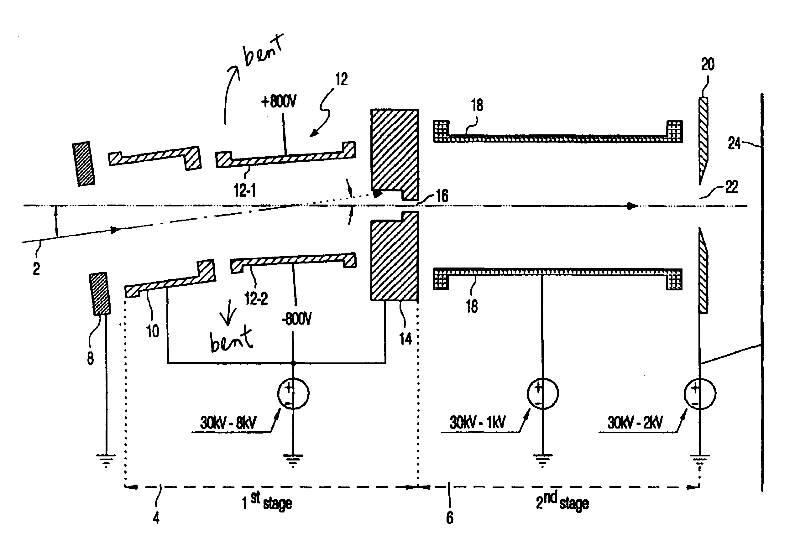
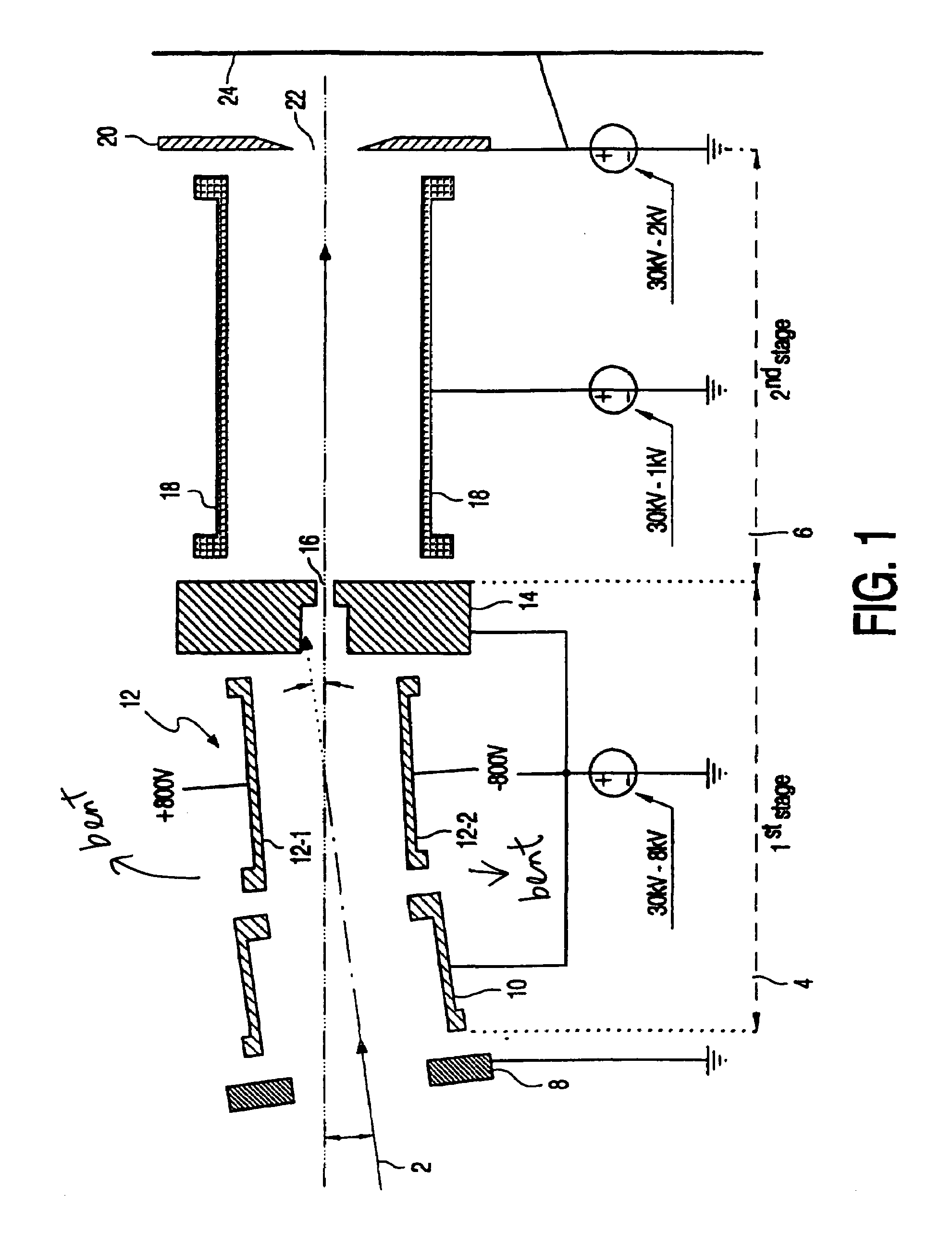
[0029]FIG. 1 is a transverse cross-sectional view showing one example of an electrostatic accelerator (Hereinafter, referred to as “electrostatic acceleration column”) in accordance with the present invention.

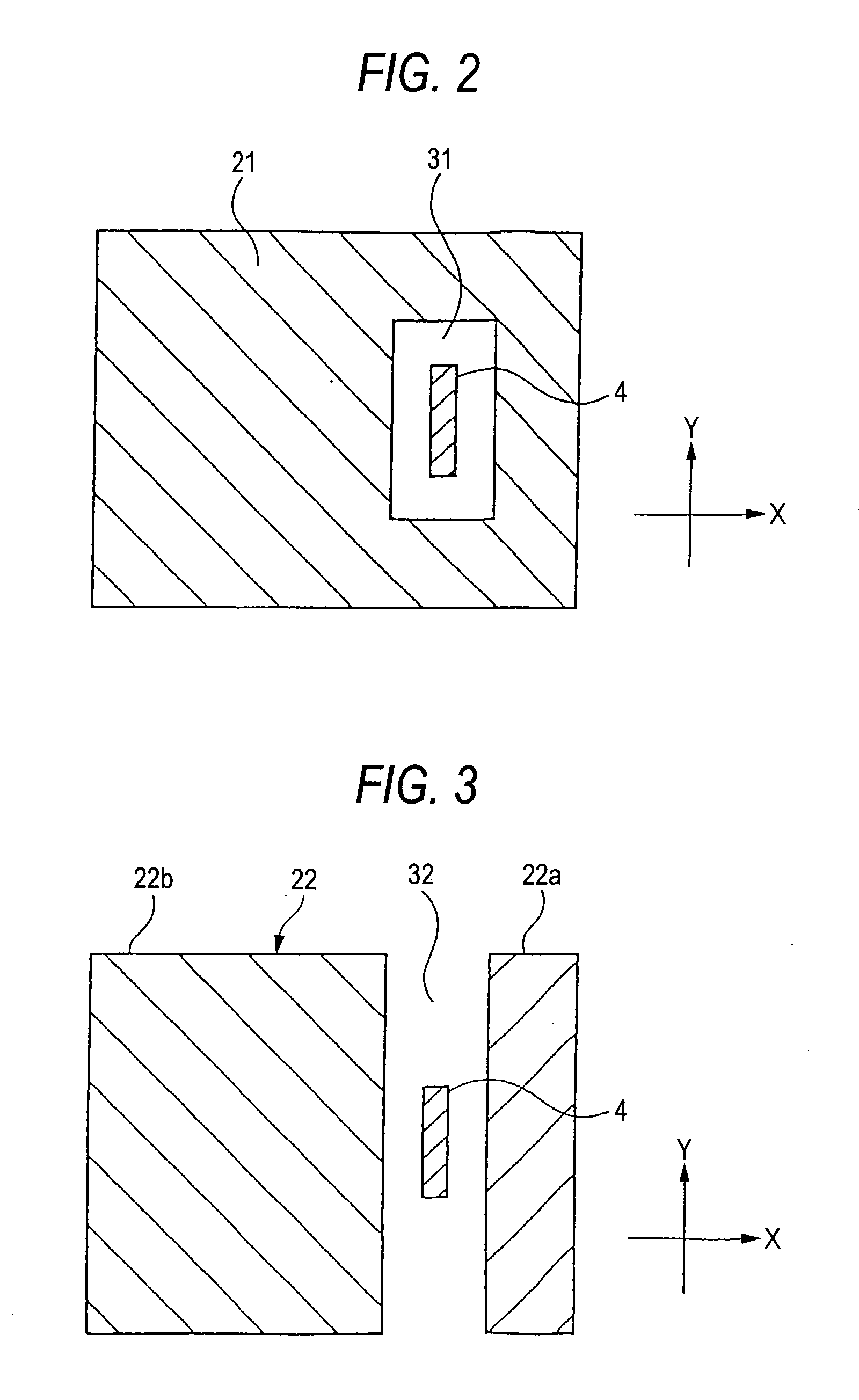
[0030]However, as for ions 4, for the sake of simplification, only a central orbit is illustrated by a line. FIG. 2 is a longitudinal cross-sectional view along a line A—A in FIG. 1. FIG. 3 is a longitudinal cross-sectional view along a line B—B in FIG. 1.

[0031]An electrostatic acceleration column 20 accelerates (in an accelerating mode) or decelerates (in a decelerating mode) ions 4. The ions 4 are a kind of charged particles.

[0032]The electrostatic acceleration column 20 has first to fifth electrodes 21 to 25 arranged in the direction of travel of the ions 4. These electrodes 21 to 25 are arranged in increasing order of number from an upstream side to a downstream side.

[0033]The ions 4 form an ion beam emitted from, for example, the above-mentioned mass separating magnet 6.

[0...


PUM


Abstract

This electrostatic acceleration column has first to fifth electrodes arranged in a traveling direction of ions, which are a kind of charged particles. Then, the second electrode divided into two electrode members, which are opposed to each other across a path of the ions, and to which different electric potentials are applied to deflect the ions. Further, the electrodes arranged on a downstream side from the electrode are arranged along an orbit of ions deflected by the electrode and having specific energy.

Description

BACKGROUND OF THE INVENTION[0001]1. Field of the Invention[0002]The present invention relates to an electrostatic accelerator (Hereinafter, referred to as “electrostatic acceleration column”) for accelerating or decelerating charged particles, and more relates to an ion implanting apparatus provided with the electrostatic acceleration column.[0003]2. Description of the Related Art[0004]One example of an ion implanting apparatus provided with a conventional electrostatic accelerator (Hereinafter, referred to as “electrostatic acceleration column”) for accelerating or decelerating ions (positive ions in the following, except where specifically noted), which are a kind of charged particles.[0005]This ion implanting apparatus is constructed as follows: ions 4 (to be more specific, an ion beam) are emitted from an ion source 2. A desired kind of ions is selected by a mass separating magnet 6. Then, the ions are accelerated or decelerated by an electrostatic acceleration column 10 to have...

Claims


Application Information

Patent Timeline
Patent Type & Authority Patents(United States)
IPC IPC(8): H01J23/00H01J37/317H05H5/00H05H7/08H05H15/00
CPCH01J37/3171H01J2237/04735H01J37/317
Inventor YAMASHITA, TAKATOSHI
Owner NISSIN ION EQUIP CO LTD
Why Eureka
Try Eureka