Electrostatic accelerator and ion implanting apparatus with the same

a technology of ion implanting apparatus and accelerator, which is applied in the direction of accelerator, direct voltage accelerator, electric discharge tube, etc., can solve the problems of increasing the loss of ions 4 and not being desirabl

Inactive Publication Date: 2003-09-18
NISSIN ION EQUIP CO LTD
View PDF4 Cites 11 Cited by
  • Summary
  • Abstract
  • Description
  • Claims
  • Application Information

AI Technical Summary

Problems solved by technology

It is not desirable in a case of utilizing charged particles such as ions that the energy contamination described above occurs.
This is because when the t

Method used


Image

  • Electrostatic accelerator and ion implanting apparatus with the same
  • Electrostatic accelerator and ion implanting apparatus with the same
  • Electrostatic accelerator and ion implanting apparatus with the same

Examples


Embodiment Construction

0 -48 0 -5 0 1 Example 130 100 52 0 -5 0 2 Example -8 0 -1 0 0 0 3

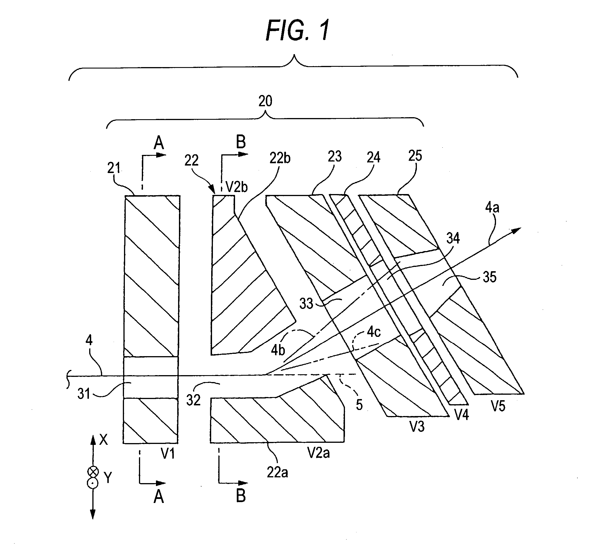
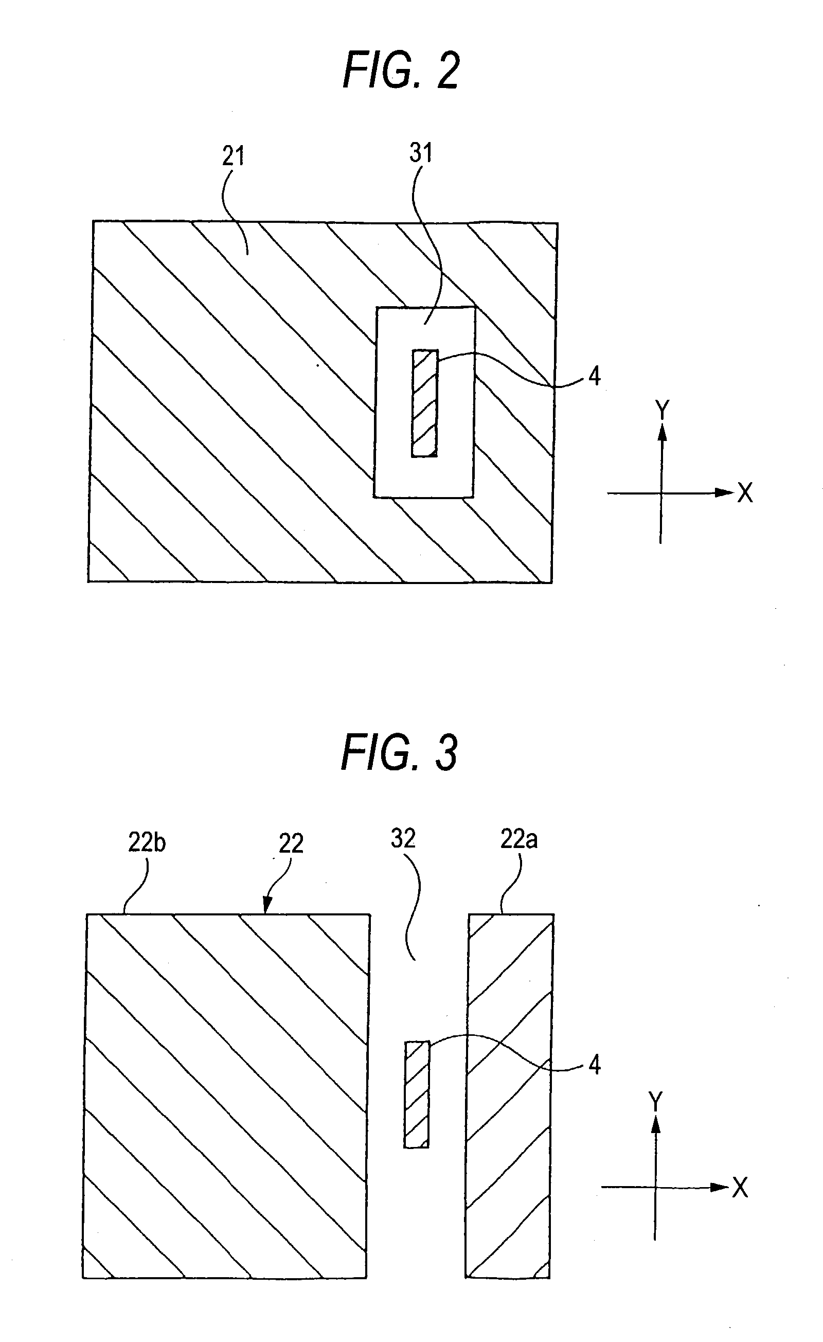
[0064] According to the above-mentioned electrostatic acceleration column 20, the second electrode 22 includes the two divided electrode members 22a and 22b, to which different electric potentials V2a and V2b are applied. The second electrode may deflect the ions 4.

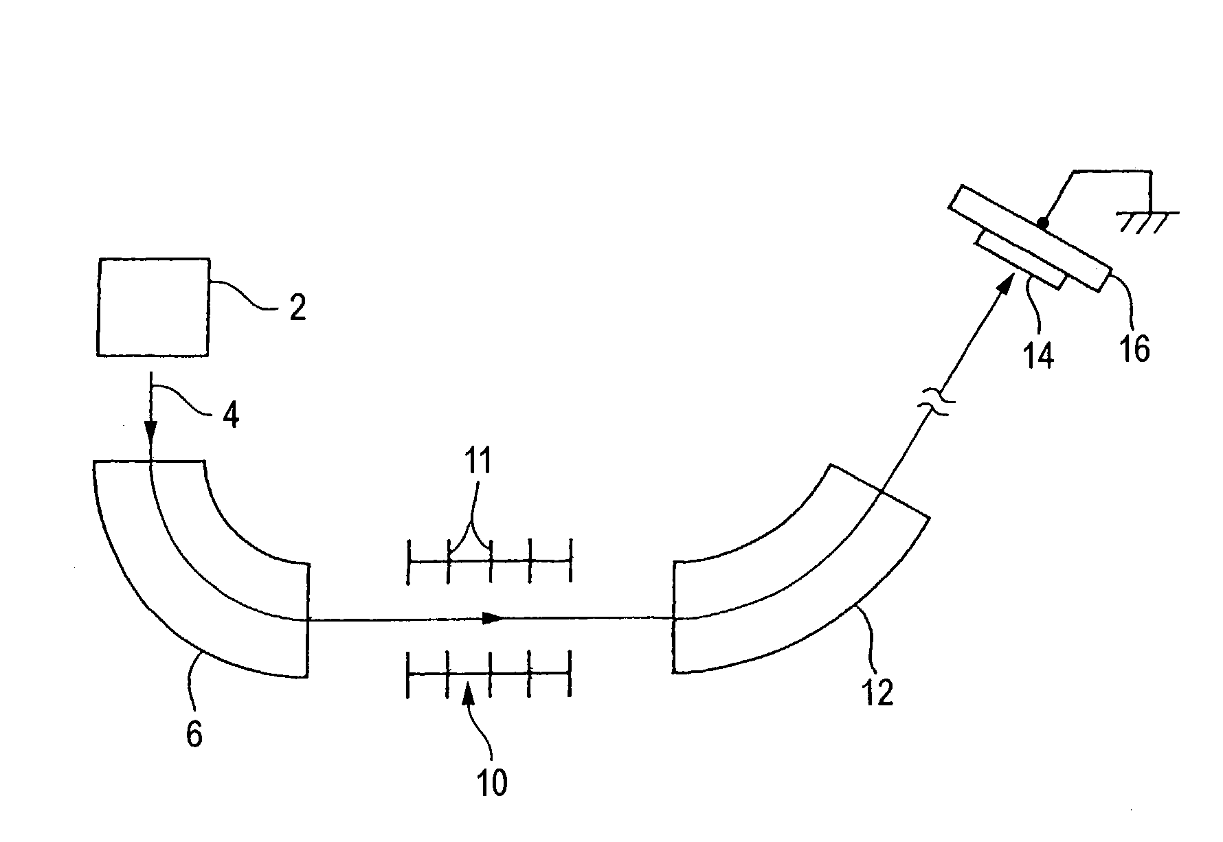
[0065] The amount of deflection at this time depends on the energy of the ions 4 when they are deflected, so that the ions 4a having desired energy can be separated from the ions 4b and 4c having energy different form the desired energy.

[0066] The ions 4b are ions having lower energy than the desired energy and are larger in the amount of deflection than the ions 4a. The ions 4c are ions having higher energy than the desired energy and are smaller in the amount of deflection than the ions 4a. The neutral particles 5 are not deflected but travel in straight lines and thus can be also separated from the ions 4a. That is, the above-mentioned electrostatic acce...


PUM


Abstract

This electrostatic acceleration column has first to fifth electrodes arranged in a traveling direction of ions, which are a kind of charged particles. Then, the second electrode divided into two electrode members, which are opposed to each other across a path of the ions, and to which different electric potentials are applied to deflect the ions. Further, the electrodes arranged on a downstream side from the electrode are arranged along an orbit of ions deflected by the electrode and having specific energy.

Description

[0001] 1. Field of the Invention[0002] The present invention relates to an electrostatic accelerator (Hereinafter, referred to as "electrostatic acceleration column") for accelerating or decelerating charged particles, and more relates to an ion implanting apparatus provided with the electrostatic acceleration column.[0003] 2. Description of the Related Art[0004] One example of an ion implanting apparatus provided with a conventional electrostatic accelerator (Hereinafter, referred to as "electrostatic acceleration column") for accelerating or decelerating ions (positive ions in the following, except where specifically noted), which are a kind of charged particles.[0005] This ion implanting apparatus is constructed as follows: ions 4 (to be more specific, an ion beam) are emitted from an ion source 2. A desired kind of ions is selected by a mass separating magnet 6. Then, the ions are accelerated or decelerated by an electrostatic acceleration column 10 to have desired energy. The d...

Claims


Application Information

Patent Timeline
IPC IPC(8): H01J23/00H01J37/317H05H5/00H05H7/08H05H15/00
CPCH01J2237/04735H01J37/3171H01J37/317
Inventor YAMASHITA, TAKATOSHI
Owner NISSIN ION EQUIP CO LTD
Why Eureka
Try Eureka