Method of changing a rotating mode between constant angular velocity and constant linear velocity

a technology of rotating mode and constant angular velocity, which is applied in the direction of digital signal error detection/correction, instruments, recording signal processing, etc., can solve the problems of data being written underrun, the property of the medium is not sufficiently changed,

Inactive Publication Date: 2006-08-29
LG ELECTRONICS INC
View PDF25 Cites 2 Cited by
  • Summary
  • Abstract
  • Description
  • Claims
  • Application Information

AI Technical Summary

Problems solved by technology

However, if the linear velocity becomes faster than a critical speed, the properties of the medium are not sufficiently changed by an incident writing beam, or data to be write becomes underrun because the data writing rate becomes higher than maximum encoding rate of an installed encoding hardware.

Method used


Image

  • Method of changing a rotating mode between constant angular velocity and constant linear velocity
  • Method of changing a rotating mode between constant angular velocity and constant linear velocity
  • Method of changing a rotating mode between constant angular velocity and constant linear velocity

Examples


Embodiment Construction

[0019]In order that the invention may be fully understood, a preferred embodiment thereof will now be described with reference to the accompanying drawings.

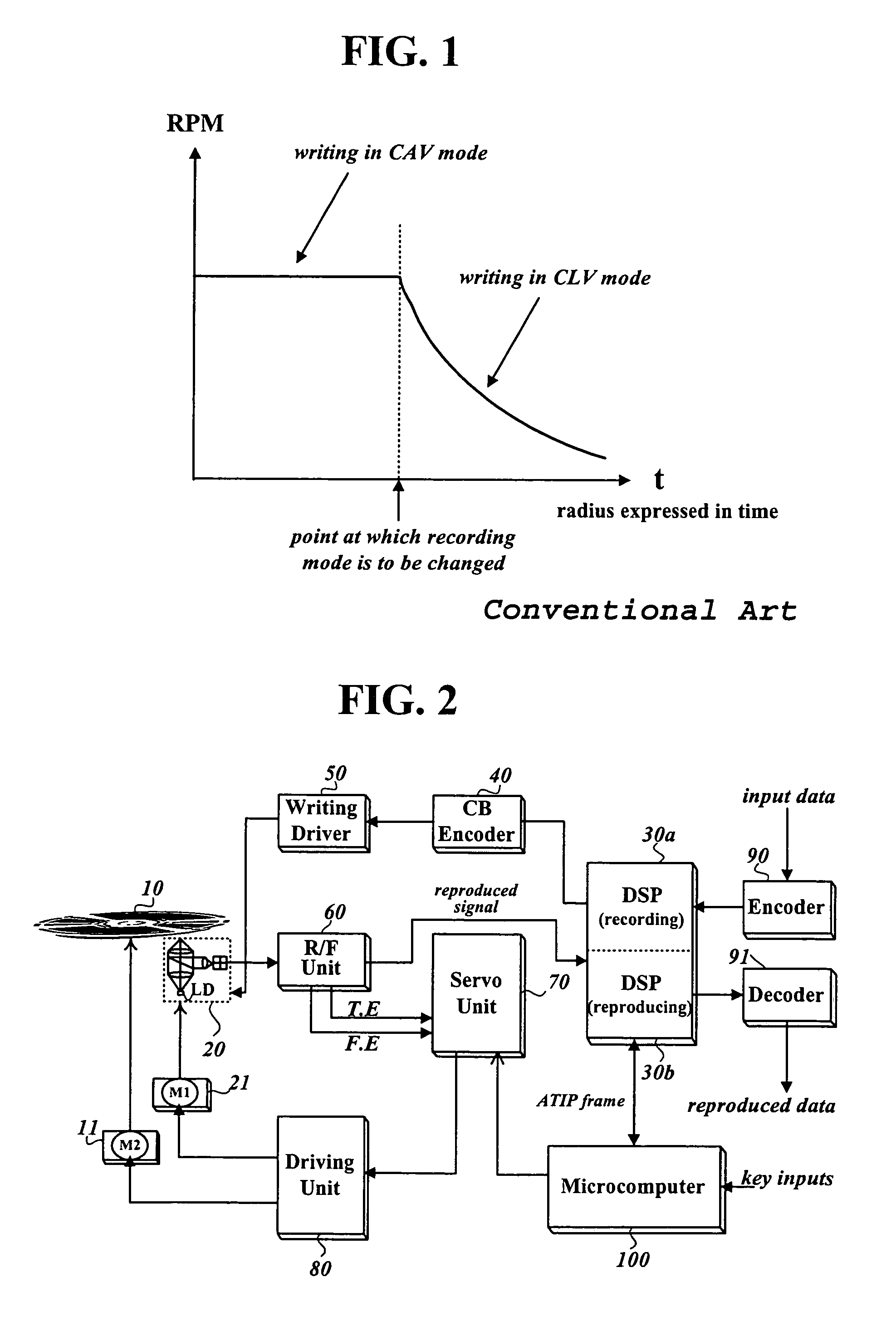
[0020]FIG. 2 is a block diagram of a disk device to which a recording mode changing method according to the present invention can be applied.

[0021]The disk device of FIG. 2 comprises an encoder 90 encoding input data; a digital recording signal processing unit 30a converting the encoded data into recording-formatted data while adding additional data such as error correction codes; a channel bit encoder 40 converting the recording-formatted data to bit streams; a writing driver 50 yielding a writing current according to an input bit stream; an optical pickup 20 writing signals corresponding to the writing current onto an optical disk 10 and reading the written signals from the optical disk 10; an R / F unit 60 yielding servo error signals TE and FE, and binary signals through combining the read signals from the disk 10; a driving un...


PUM

PropertyMeasurementUnit
Constant Angular Velocityaaaaaaaaaa
Constant Linear Velocityaaaaaaaaaa
frequencyaaaaaaaaaa

Abstract

The present invention relates to a method of changing a recording mode from CAV (Constant Angular Velocity) mode to CLV (Constant Linear Velocity) mode in the middle of recording data to a disk recording medium. A method according to the present invention reads ATIP-framed data encoded in a wobble signal formed along a spiral physical track while recording input data to a recording medium, and detects a sync signal contained in the read ATIP-framed data. Another method measures the frequency of a low-frequency component of the wobble signal instead of reading ATIP-framed data. These two methods determine, in common, when to change the recording mode from CAV to CLV based on the period of the detected sync signal or the measured frequency. The present invention makes it possible to record input data to an entire area of a disk more rapidly without fatal errors such as imperfect writing. As a result, total recording time can be reduced with stable recording guaranteed.

Description

BACKGROUND OF THE INVENTION[0001]1. Field of the Invention[0002]The present invention relates to a method of changing a recording mode from CAV (Constant Angular Velocity) to CLV (Constant Linear Velocity) in the middle of recording data to a disk recording medium.[0003]2. Description of the Related Art[0004]In general, a disk recording device writes input data at a speed slower than 2×, so that it writes data to a writable disk such as CD-R and CD-RW at CAV mode for entire recording area of the disk.[0005]In the meantime, the recording speed of a disk recording devices are becoming increasingly faster, which requires faster rotation speed of a writable disk. In the CAV mode, the linear velocity is increased in proportion to a radius as a recording point goes outward. However, if the linear velocity becomes faster than a critical speed, the properties of the medium are not sufficiently changed by an incident writing beam, or data to be write becomes underrun because the data writing...

Claims


Application Information

Patent Timeline
Patent Type & Authority Patents(United States)
IPC IPC(8): G11B15/46G11B7/0045G11B19/28
CPCG11B19/28G11B7/0045G11B7/007
Inventor JIN, CHEOL
Owner LG ELECTRONICS INC
Why Eureka
Try Eureka