
Developing roller, electrophotographic process cartridge, and electrophotographic image forming apparatus

a technology of developing rollers and process cartridges, applied in the direction of electrographic process equipment, shafts and bearings, instruments, etc., can solve the problems of unresolved problems concerning uniformity of charging and running stability of charging, and difficult subjects to obtain high-grade images that can achieve high image density

Active Publication Date: 2006-08-29
CANON KK
View PDF16 Cites 11 Cited by
  • Summary
  • Abstract
  • Description
  • Claims
  • Application Information

AI Technical Summary

Benefits of technology

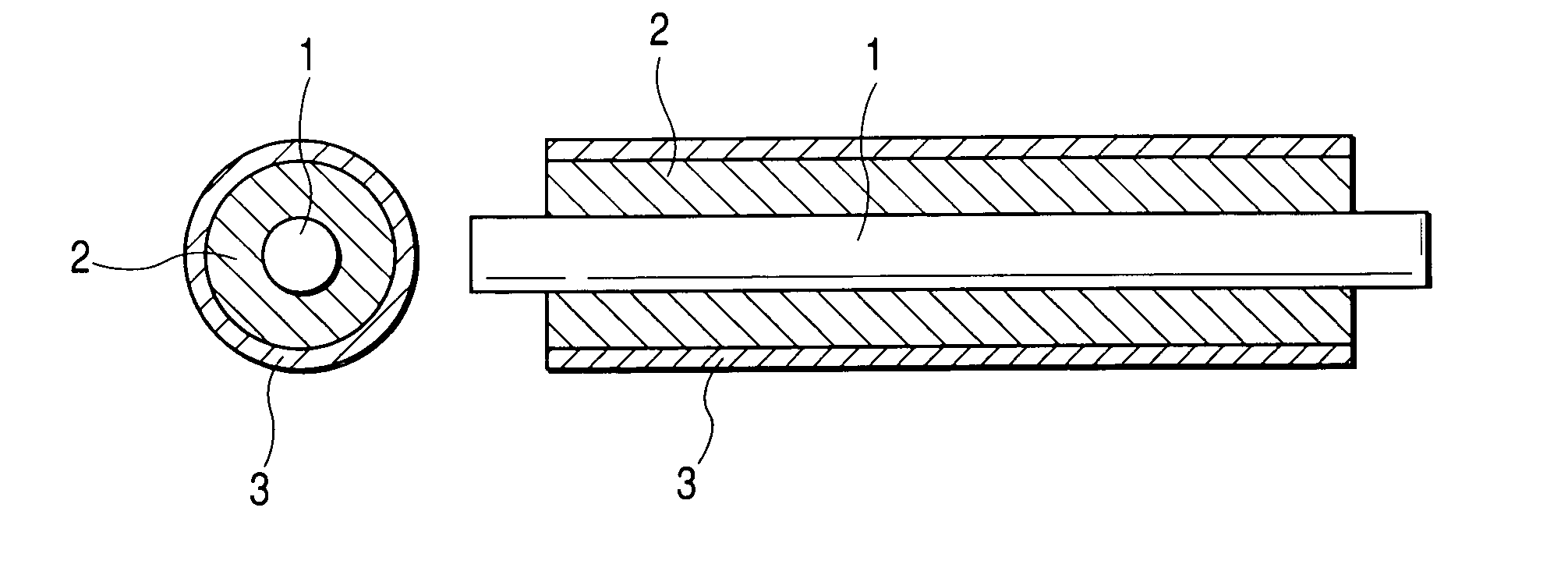
[0007]The present invention has been made taking into account the above-described subject. Accordingly, an object of the present invention is to provide a developing roller that can effectively keep ghosts from occurring and can achieve high image density in the low-temperature and low-humidity environment.
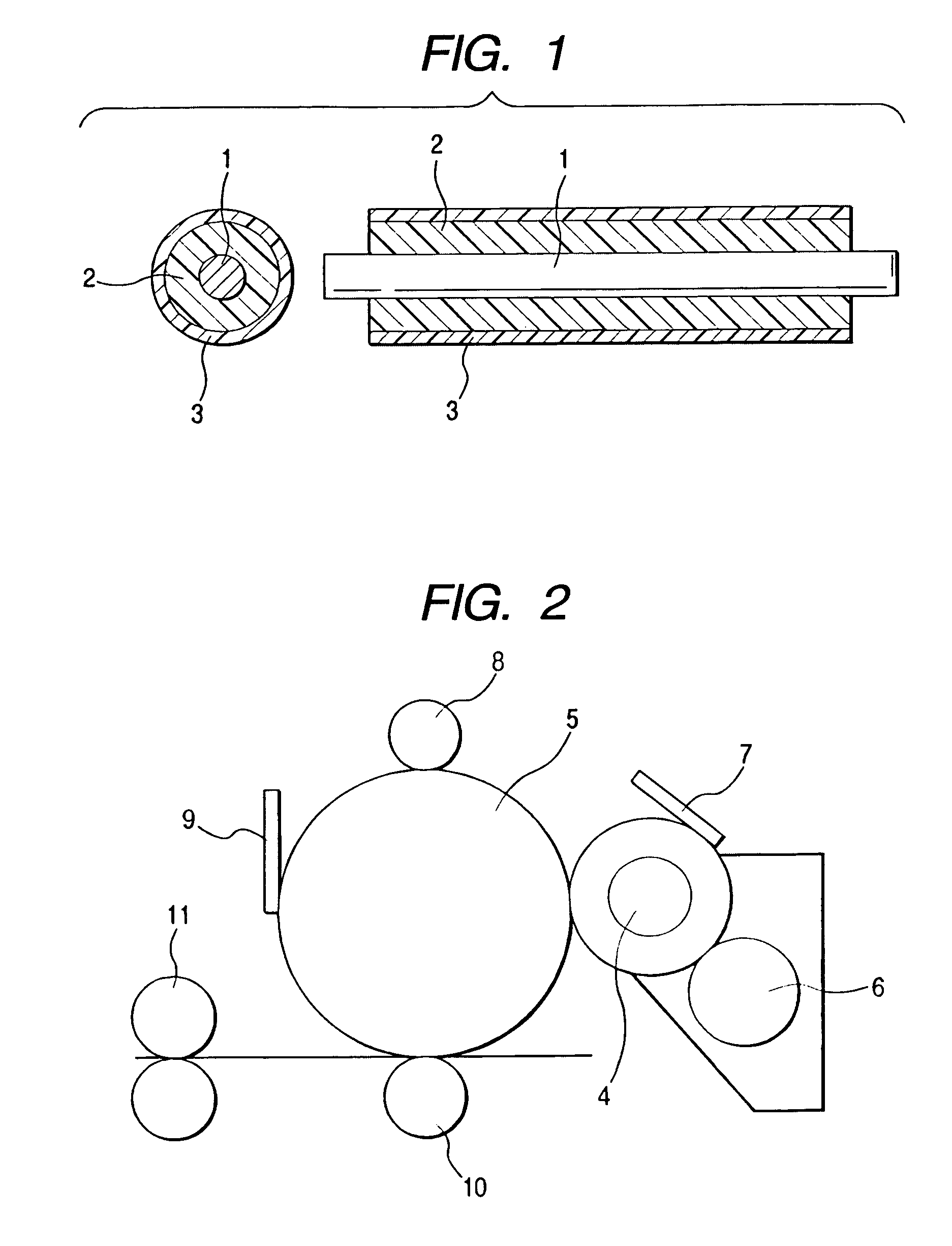
[0008]Another object of the present invention is to provide an electrophotographic process cartridge and an electrophotographic image forming apparatus that can effectively keep ghosts from occurring.
[0010]In the present invention, the most-surface layer of the developing roller is covered with a conductive resin containing a condensed polycyclic organic pigment. This enables formation of high-grade images free of ghosts, and at the same time stabilization of the quantity of toner on the developing roller in the low-temperature and low-humidity environment to achieve proper image density.

Problems solved by technology

However, where the non-magnetic one-component developer is used in conjunction with conventional developing rollers, it is difficult to control the charging of toner on the developing rollers, and problems concerning uniformity of charging and running stability of charging have not completely been solved, where image defects such as ghosts may occur.
In this case, it is a difficult subject to obtain high-grade images that can achieve high image density especially in a low-temperature and low-humidity environment (15° C., 10% RH).

Method used


Image

  • Developing roller, electrophotographic process cartridge, and electrophotographic image forming apparatus
  • Developing roller, electrophotographic process cartridge, and electrophotographic image forming apparatus

Examples


example 1

[0041]A mandrel of 8 mm in outer diameter was concentrically set in a cylindrical mold of 16 mm in inner diameter, and, to form a conductive elastic layer, liquid conductive silicone rubber (a product available from Dow Corning Toray Silicone Co., Ltd.; ASKER-C hardness: 40°; volume resistivity: 107 Ω·cm) was cast into it. Thereafter, this was put into a 130° C. oven, and was heated for 20 minutes to carry out molding. After demolding, the molded product was subjected to secondary vulcanization for 4 hours in a 200° C. oven to obtain a roller having a conductive elastic layer of 4 mm in thickness.

[0042]Next, a urethane coating material (trade name: NIPPOLAN N5037; available from Nippon Polyurethane Industry Co., Ltd.) was diluted with methyl ethyl ketone so as to be in a solid-matter concentration of 10%, and added thereto were carbon black (trade name: MA-230; available from Mitsubishi Chemical Corporation) as a conductive material in an amount of 15 parts by weight, C.I. Pigment R...

example 2

[0043]A developing roller was obtained in the same manner as in Example 1 except that the condensed polycyclic organic pigment was changed to C.I. Pigment Blue 60 (available from Ciba Specialty Chemicals.). The developing roller obtained had a surface roughness Rz of 5.4 μm.

example 3

[0044]A developing roller was obtained in the same manner as in Example 1 except that the condensed polycyclic organic pigment was changed to C.I. Pigment Violet 19 (available from Ciba Specialty Chemicals.). The developing roller obtained had a surface roughness Rz of 5.2 μm.


PUM


Abstract

In a developing roller having a shaft member, a conductive elastic layer provided on the shaft member, and a conductive resin layer constituting a most-surface layer, the conductive resin layer contains a condensed polycyclic organic pigment as exemplified by at least one selected from the group consisting of a quinacridone pigment, a threne pigment, a perylene pigment and a perinone pigment. The developing roller can effectively keep ghosts from occurring and can achieve high image density in a low-temperature and low-humidity environment.

Description

BACKGROUND OF THE INVENTION[0001]1. Field of the Invention[0002]This invention relates to a developing roller which is used in, e.g., electrophotographic apparatus such as copying machines and laser beam printers, and to an electrophotographic process cartridge and an electrophotographic image forming apparatus which make use of the developing roller.[0003]2. Related Background Art[0004]Conventionally, in electrophotographic apparatus or electrostatic recording apparatus, such as copying machines and laser beam printers, a pressure developing method is known as a developing method in which a non-magnetic one-component developer is fed to, e.g., a photosensitive drum which is holding a latent image thereon and the developer is made to adhere to the latent image (electrostatically charged image) on the photosensitive drum to render the latent image visible. According to this method, any magnetic material is not required, and hence the image forming apparatus can be made simple or comp...

Claims


Application Information

Patent Timeline
Patent Type & Authority Patents(United States)
IPC IPC(8): G03G15/08F16C13/00G03G15/00G03G15/06G03G21/16
CPCG03G15/0818G03G2215/0861G03G15/0808G03G21/181G03G21/1814G03G21/1817G03G21/1867
Inventor NAKAMURA, MINORUYAMAMOTO, ARIHIROISHIDA, KAZUTOSHI
Owner CANON KK
Learn More