Electrophotographic photoreceptor, and image forming apparatus and process cartridge using the same

a photoreceptor and electrophoresis technology, applied in electrophoresis, instruments, corona discharge, etc., can solve the problems of difficult to completely remove toner particles by brush cleaner, easy absorption or scratching of organic photoreceptors after long repeated use, and poor mechanical durability. , to achieve the effect of good combination of mechanical durability and oxidizing gas resistan

Inactive Publication Date: 2007-09-13
RICOH KK
View PDF59 Cites 42 Cited by
  • Summary
  • Abstract
  • Description
  • Claims
  • Application Information

AI Technical Summary

Benefits of technology

[0027]Accordingly, exemplary aspects of the present invention provide an electrophotographic pho

Problems solved by technology

On the other hand, organic photoreceptors are easily abraded or scratched after long repeated use because of having poor physical and chemical strength.
Such toner particles remaining on the surface of the photoreceptor contribute to image deterioration.
However, it is difficult to completely remove toner particles by the brush cleaner because ultrafine particles tend to slip through fibers.
In this case, there is a problem that toner particles tend to be scattered due to the electrostatic force and then adhere to the photoreceptor again.
Therefore, the surface of the photoreceptor tends to be mechanically abraded or scratched.
When such a charger is used, magnetic particles of the magnetic brush are involuntarily transferred onto the photoreceptor, and then pressed thereon in the transfer process and the cleaning process, resulting in scratches being made on the surface of the photoreceptor.
However, these attempts are not enough to improve mechanical durability and electric property of an electrophotographic photoreceptor.
However, no mention is made of a charge transport material used together therewith.
In this case, the low-molecular-weight components may bleed out and mechanical strength of the outermost layer may deteriorate.
As a result, mechanical durability and abrasion resistance of the resultant photoreceptor deteriorate.
However, such a thin outermost layer may disappear by abrasion in a short time.
Therefore, such a photoreceptor having a thin outermost layer cannot be a long-life photoreceptor.
However, when the above compound having no reactivity is used as the binder resin, the binder resin and the reaction product of the monomer with the charge transport material may have poor compatibility, and therefore the layer tend to separate and decrease the smoothness of the surface.
As a result, the resultant photoreceptor has poor cleanability and the resultant image quality deteriorates.
As specific examples of the compound having reactivity, difunctional compounds are disclosed therein, but it is difficult to obtain a high cross-linking density by using these compounds, and therefore the resultant photoreceptor has poor abrasion resistance.
Even if a photoreceptor having good mechanical durability is

Method used


Image

  • Electrophotographic photoreceptor, and image forming apparatus and process cartridge using the same
  • Electrophotographic photoreceptor, and image forming apparatus and process cartridge using the same
  • Electrophotographic photoreceptor, and image forming apparatus and process cartridge using the same

Examples


example 1

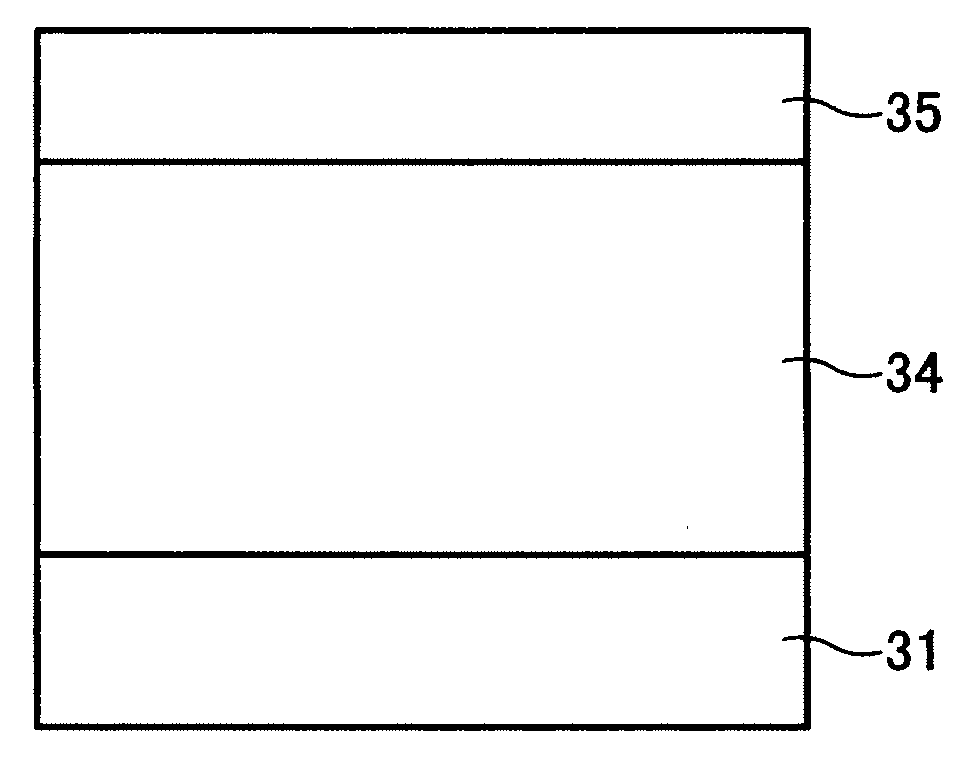
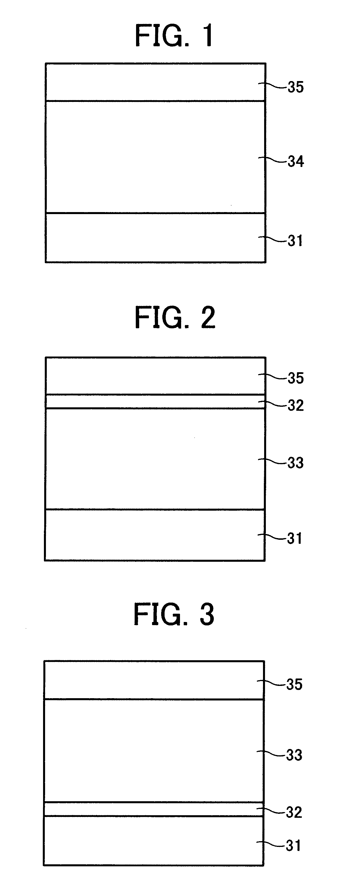
[0230]On an aluminum cylinder having a diameter of 30 mm, an undercoat layer coating liquid, a charge generation layer coating liquid, a charge transport layer coating liquid having the following compositions were coated in this order, followed by drying. Thus, an undercoat layer having a thickness of 3.5 μm, a charge generation layer having a thickness of 0.2 μm, and a charge transport layer having a thickness of 18 μm were prepared.

Undercoat Layer Coating LiquidAlkyd resin 6 parts(BECKOSOL ® 1307-60-EL from DainipponInk and Chemicals, Incorporated)Melamine resin 4 parts(SUPER BECKAMINE ® G-821-60 fromDainippon Ink and Chemicals, Incorporated)Titanium oxide40 partsMethyl ethyl ketone50 parts

Charge Generation Layer Coating LiquidBisazo pigment having the following formula (i)2.5partsPolyvinyl butyral0.5parts(XYHL from UCC)Cyclohexanone200partsMethyl ethyl ketone80parts

Charge Transport Layer Coating LiquidBisphenol Z polycarbonate10parts(PANLITE ® TS-2050 from Teijin Chemicals Ltd.)L...

example 2

[0233]The procedure for preparation of the photoreceptor in Example 1 was repeated except that the radical polymerizable compound having no charge transport structure was replaced with a caprolactone modified dipentaerythritol hexaacrylate (KAYARAD DPCA-120 from Nippon Kayaku Co., Ltd.) having the following formula (iv).

[0234]Thus, a photoreceptor (2) was prepared.

example 3

[0235]The procedure for preparation of the photoreceptor in Example 1 was repeated except that the radical polymerizable compound having no charge transport structure was replaced with a mixture in which the dipentaerythritol hexaacrylate (KAYARAD DPHA from Nippon Kayaku Co., Ltd.) having the formula (iii) and a trimethylolpropane triacrylate (TMPTA from Tokyo Chemical Industry Co., Ltd.) having the following formula (v) were mixed at a mixing ratio of 1 / 1 by weight.

[0236]Thus, a photoreceptor (3) was prepared.


PUM

PropertyMeasurementUnit
Thicknessaaaaaaaaaa
Temperatureaaaaaaaaaa
Fractionaaaaaaaaaa

Abstract

An electrophotographic photoreceptor is provided including an electroconductive substrate; a photosensitive layer located overlying the electroconductive substrate; and an outermost layer located overlying the photosensitive layer, wherein the outermost layer is formed by a reaction between a radical polymerizable compound having no charge transport structure including a compound having a specific formula, and a radical polymerizable compound having a charge transport structure, while applying heat, light, or ionizing radiation to the reaction, and wherein at least one of the photosensitive layer and the outermost layer includes at least an arylmethane compound having an alkylamino group or a compound having a specific formula.

Description

CROSS-REFERENCE TO RELATED APPLICATIONS[0001]This document claims priority and contains subject matter related to Japanese Patent Applications Nos. 2006-066518, 2006-066552, and 2006-069169, filed on Mar. 10, 2006, Mar. 10, 2006, and Mar. 14, 2006, respectively, the entire contents of each of which are incorporated herein by reference.BACKGROUND OF THE INVENTION[0002]1. Field of the Invention[0003]Exemplary aspects of the present invention relate to an electrophotographic photoreceptor. In addition, exemplary aspects of the present invention relate to an image forming apparatus and a process cartridge using the electrophotographic photoreceptor.[0004]2. Description of the Related Art[0005]Organic photoreceptors are widely used as an electrophotographic photoreceptor (hereinafter referred to as photoreceptor). Organic photoreceptors typically have the following advantages over inorganic photoreceptors.[0006]Organic photoreceptors are capable of using materials responsive to various l...

Claims


Application Information

Patent Timeline
IPC IPC(8): G03G5/047G03G5/147
CPCG03G5/0542G03G5/0546G03G5/0589G03G5/0592G03G5/0596G03G5/14795G03G5/1473G03G5/14734G03G5/14786G03G5/14791G03G5/071G03G5/0745G03G5/0732G03G5/072G03G5/074G03G5/0763
Inventor TOSHINE, TETSUYASUZUKI, YASUOSUZUKI, TETSUROKAMI, HIDETOSHIFUJIWARA, YUKIOINABA, YOSHINORI
Owner RICOH KK
Why Eureka
Try Eureka