Point-to-point electrical loading for a multi-drop bus

a multi-drop bus and point-to-point technology, applied in the direction of electrical devices, electric digital data processing, instruments, etc., can solve the problems of increasing the total system cost, imposing costs on the system designer, and requiring multiple bridges imposing additional space costs

Inactive Publication Date: 2006-08-29
HEWLETT PACKARD DEV CO LP
View PDF8 Cites 5 Cited by
  • Summary
  • Abstract
  • Description
  • Claims
  • Application Information

AI Technical Summary

Benefits of technology

[0015]In a further embodiment, the first switch and the second switch are packaged together as a unit. In another further embodiment, the first switch and the second switch are Field Effect Transistor (FET) switches.

Problems solved by technology

Fewer numbers of faster devices than slower devices can be connected to a given bus segment.
Such a limitation may impose costs on system designers.
Limiting a bus segment to a single interconnect device means that each slot typically has its own sourcing bridge / host bridge per slot, increasing total system costs.
In addition, the requirement for multiple bridges imposes additional space costs.

Method used


Image

  • Point-to-point electrical loading for a multi-drop bus
  • Point-to-point electrical loading for a multi-drop bus
  • Point-to-point electrical loading for a multi-drop bus

Examples


Embodiment Construction

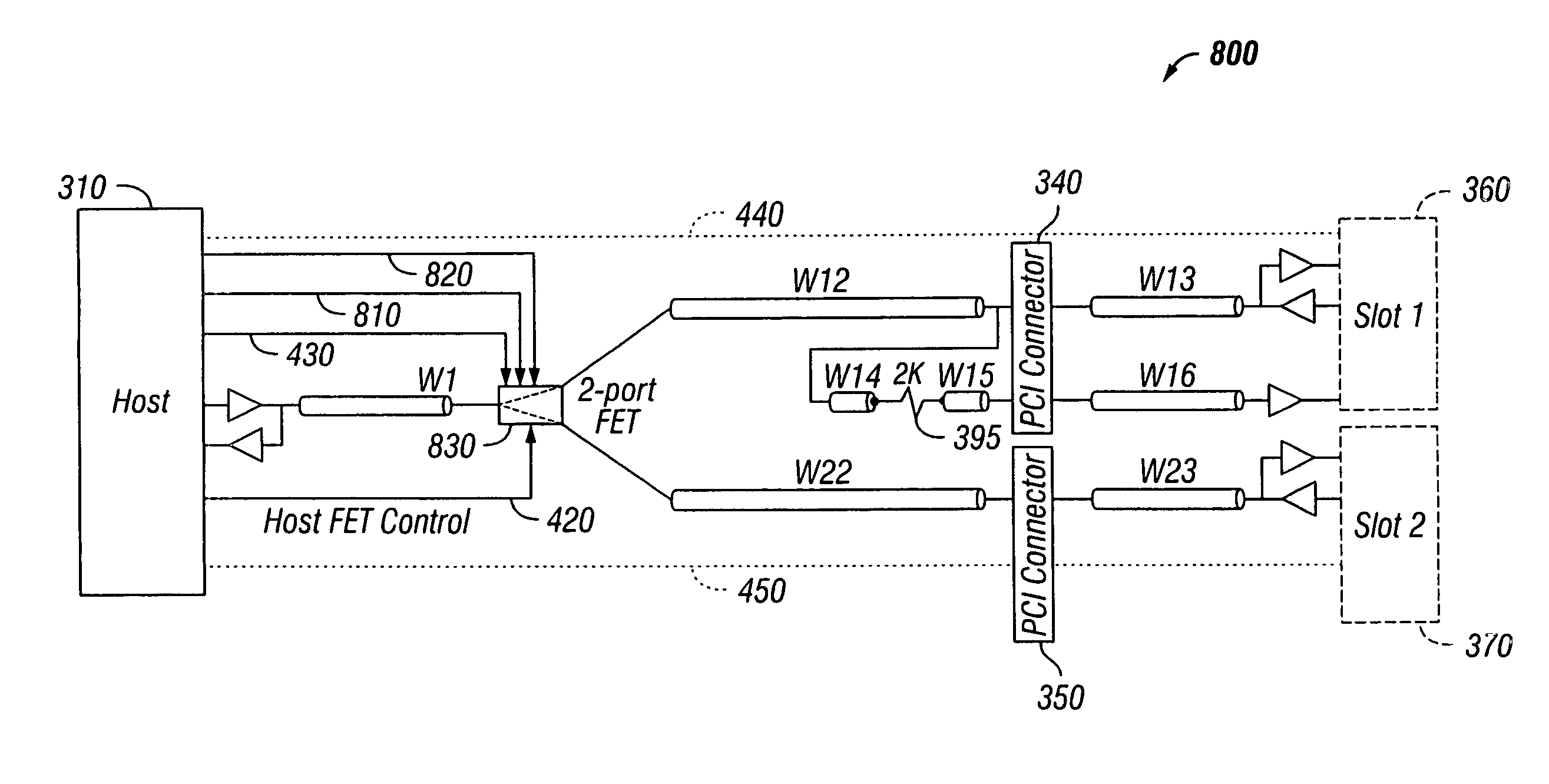
[0035]The present invention provides a technique for enhancing the operation of computer system busses that use the extensions to the Peripheral Component Interconnect specification (hereinafter PCI-X busses), as well as logic circuits and signal protocols thereof. For illustrative purposes, embodiments are described herein for computer systems using Intel Corporation microprocessor architectures and certain terms and references are specific to such processor platforms. PCI-X and the enhancements described herein, however, are hardware independent, and may be used with any host computer designed for this interconnect standard. As will be appreciated by those skilled in the art of computer systems, the disclosed embodiments can be adapted and applied to any computer platform utilizing the PCI-X standard. Further, although the following is described in terms of PCI-X busses, other bus architectures and protocols, such as the 3GIO bus architecture and protocol being promoted by Intel C...


PUM


Abstract

A switching technique allows multiple interconnect bus devices to be connected to a single bus segment, even if the interconnect bus protocol only allows a one of the interconnect devices to be connected at any time. Each of the interconnect devices is connected to the interconnect bus segment with a switch, such that the interconnect device is electrically isolated from the interconnect bus segment when the switch is open. An interconnect sourcing agent connected to the interconnect bus segment controls the switches, closing the switch for one of the interconnect devices when a transaction is destined for that interconnect device, opening all of the other switches so that only one device is connected to the bus at any time.

Description

CROSS-REFERENCE TO RELATED APPLICATIONS[0001]This application is related to the following commonly owned U.S. patents and patent applications, which are hereby incorporated in their entirety by reference for all purposes:[0002]U.S. Pat. No. 6,266,731, entitled “HIGH SPEED PERIPHERAL INTERCONNECT APPARATUS, METHOD AND SYSTEM,” by Dwight Riley and Christopher J. Pettey; and[0003]U.S. patent application Ser. No. 09 / 747,422, now U.S. Pat. No. 6,557,068, entitled “HIGH SPEED PERIPHERAL INTERCONNECT APPARATUS, METHOD AND SYSTEM,” by Dwight Riley and Christopher J. Pettey, filed Dec. 22, 2000.STATEMENTS REGARDING FEDERALLY SPONSORED RESEARCH OR DEVELOPMENT[0004]Not applicable.REFERENCE TO A MICROFICHE APPENDIX[0005]Not applicable.BACKGROUND OF THE INVENTION[0006]1. Field of the Invention[0007]The present invention is related to interconnect busses of computer systems and in particular to dynamically connecting multiple devices to an interconnect bus such that only a single one of the multi...

Claims


Application Information

Patent Timeline
Patent Type & Authority Patents(United States)
IPC IPC(8): G06F13/00G06F13/40
CPCG06F13/4068
Inventor CHAN, MICHAEL Y.RILEY, DWIGHT D.
Owner HEWLETT PACKARD DEV CO LP
Why Eureka
Try Eureka