Disengageable ski binding

a ski binding and disengageable technology, applied in the direction of ski bindings, skiing, sport apparatus, etc., to achieve the effect of ensuring disengagement and elasticity behavior, and good

Inactive Publication Date: 2006-09-05
MARKER DEUTLAND
View PDF9 Cites 8 Cited by
  • Summary
  • Abstract
  • Description
  • Claims
  • Application Information

AI Technical Summary

Benefits of technology

[0009]It is an object of the invention, then, in the case of a ski binding, to ensure d

Problems solved by technology

This is achieved, in the first instance, in that rotary movements of the standing and/or carrying plate about the vertical axis which are caused by disruptive forces, on account of the first and second latching devices being sepa

Method used


Image

  • Disengageable ski binding
  • Disengageable ski binding
  • Disengageable ski binding

Examples


Embodiment Construction

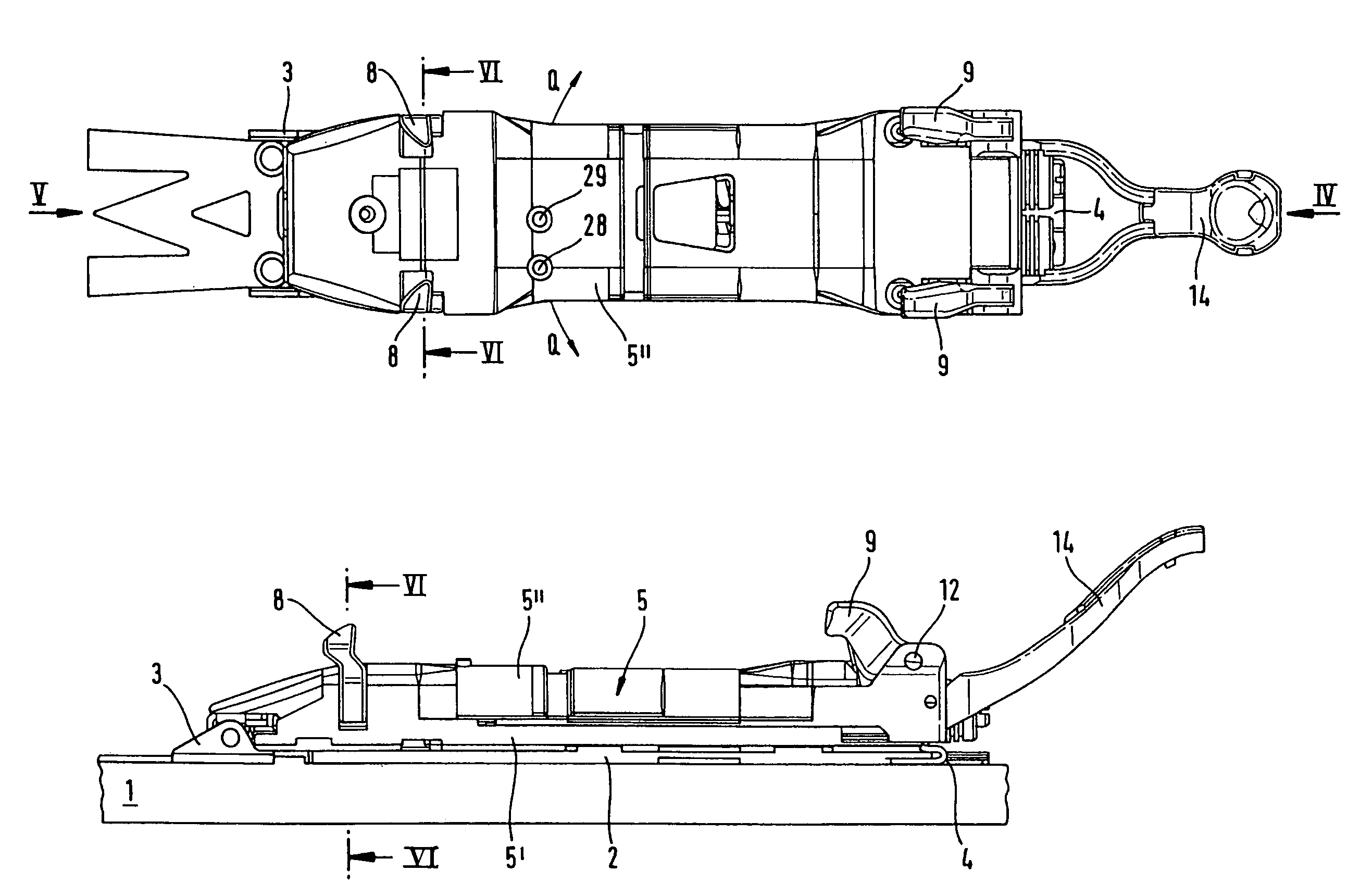
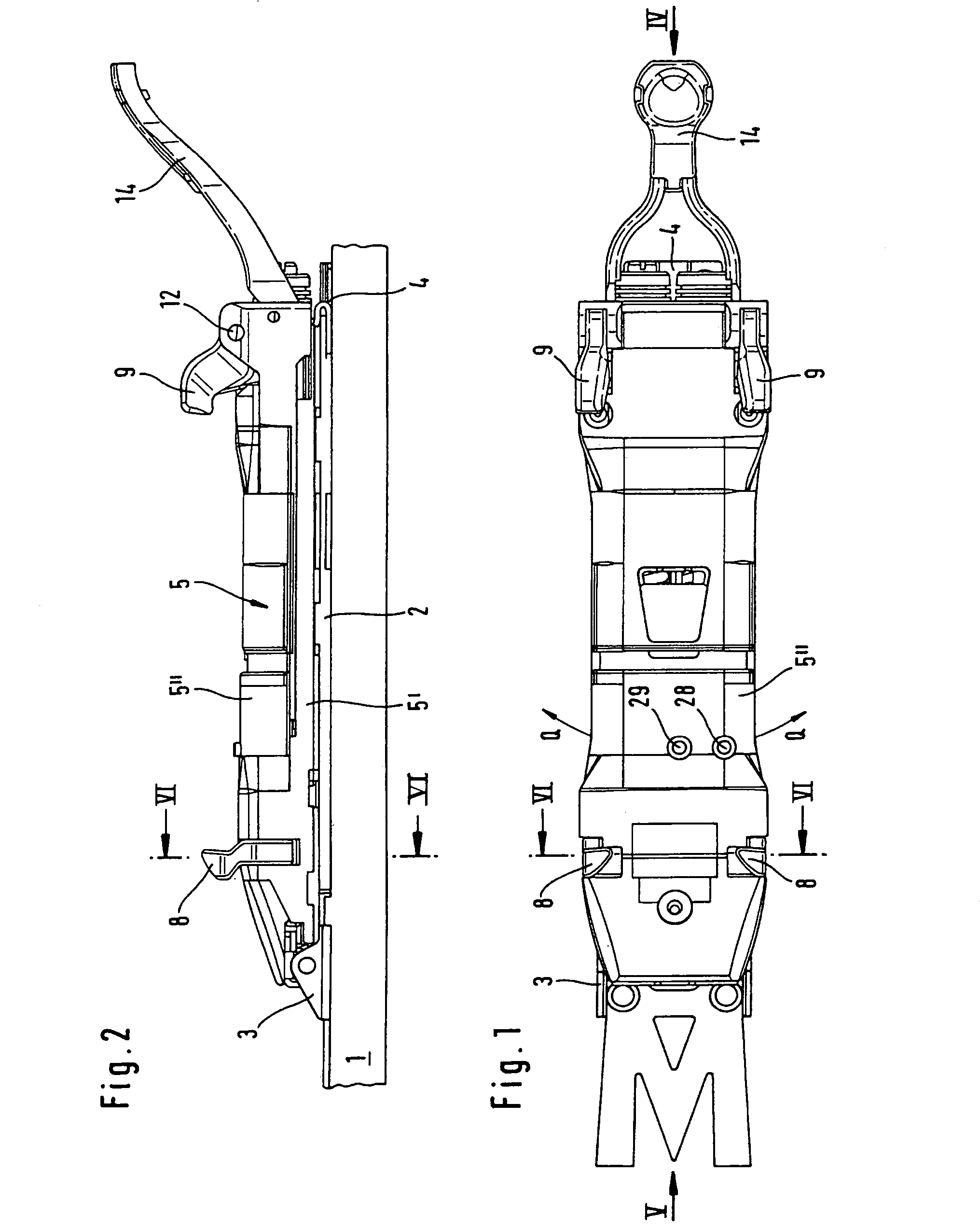
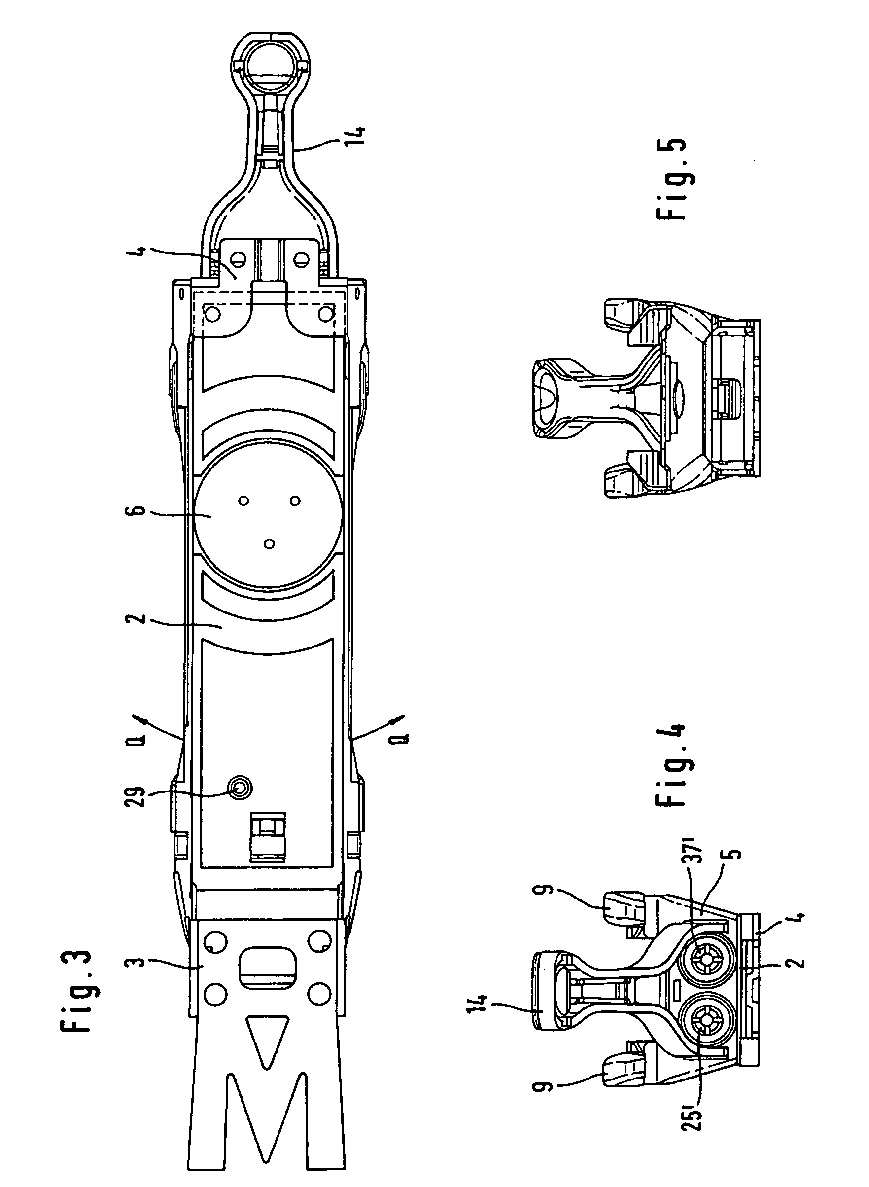
[0027]The binding according to the invention has a base plate 2 which is arranged on a ski 1, indicated partly in FIG. 2, which is connected at its front end, as seen in the longitudinal direction of the ski, in a hinge-like manner to a bearing part 3, arranged firmly on the ski, such that it can be pivoted about a transverse ski axis, and which is secured vertically, with displaceability in the longitudinal direction of the ski, at its rear end, as seen in the longitudinal direction of the ski, in a further ski-mounted bearing part 4.

[0028]Arranged on the base plate 2 is a standing and / or carrying plate 5, which can be rotated about a vertical axis of the base plate 2 and of which the top side serves as a standing and / or supporting surface for the sole of a ski boot which is to be inserted into the ski binding. The standing and / or carrying plate 5 has a bottom plate part 5′, designed as a frame and structural part, and a covering part 5″ on the top side. The abovementioned connecti...


PUM


Abstract

Disengageable ski binding having a carrying plate which is provided as a standing surface for a ski boot and is arranged on a ski-mounted base part such that it can be rotated about a vertical axis of the base part counter to an adjustable resistance of a first latching device, and having disengageable front and rear sole holders which are arranged on the carrying plate, it being the case that the rear sole holders can be disengaged counter to an adjustable resistance of a second latching arrangement, which is separate from the first latching device, and/or the front sole holders are locked within a predetermined angle-of-rotation region of the carrying plate, without affecting the resistance of the first latching device, and are unlocked outside the region of rotation.

Description

BACKGROUND OF THE INVENTION[0001]1. Field of the Invention[0002]The invention relates to a disengageable ski binding.[0003]1. Description of the Prior Art[0004]In the case of virtually all ski bindings which are currently available on the market, a front boot-retaining unit and a rear boot-retaining unit are arranged on the ski, the front boot-retaining unit interacting in a form-fitting manner with the toe end, and the rear boot-retaining unit interacting in a form-fitting manner with the heel end, of the “standard” sole of a ski boot. To be precise, the front boot-retaining unit prevents the toe end of the sole from moving forward in the longitudinal direction of the ski and from moving in the direction of the vertical and transverse axes of the ski, while the rear boot-retaining unit secures the heel end of the sole against moving rearward in the longitudinal direction of the ski and against moving in the direction of the vertical and transverse axes of the ski.[0005]Such binding...

Claims


Application Information

Patent Timeline
IPC IPC(8): A63C9/00A63C9/08A63C9/084A63C9/085A63C9/086
CPCA63C9/0805A63C9/0807A63C9/0842A63C9/086A63C9/08528A63C9/08564A63C9/0847
Inventor KRUMBECK, MARKUSMANGOLD, MICHAELMANN, ANDREAS
Owner MARKER DEUTLAND
Why Eureka
Try Eureka