Multi hull barge

a multi-hull barge and hull technology, applied in special-purpose vessels, vessel parts, vessel construction, etc., can solve the problems of reducing stability, lng tanks occupying the majority of available deck space, and high center of mass, so as to avoid potentially dangerous situations and be safe to use

Inactive Publication Date: 2006-09-05
SINGLE BUOY MOORINGS INC
View PDF20 Cites 18 Cited by
  • Summary
  • Abstract
  • Description
  • Claims
  • Application Information

AI Technical Summary

Benefits of technology

[0018]The turret structure to which anchor lines extending from the seabed and / or product risers are connected may be situated at the bow of the vessel or between the hulls such that the vessel can rotatably weathervane around the turret. The advantage of turret mooring is that the turret need not be placed through a hull structure. In a regular vessel having a single hull and a turret extending through the hull, the tanks in the vicinity of the turret could not be allowed to be filled with LNG from a safety point of view. By the design of the present invention, wherein the turret is situated between the two hulls, the tanks in the hulls in the vicinity of the turret can be safely employed.
[0019]Preferably, the deck structure of the vessel is substantially closed, such that spills of hydrocarbons will not fall directly into the water. In case LNG is stored in the tanks, a closed deck avoids potentially dangerous situations created by LNG spills.

Problems solved by technology

The known LNG tanker has a high center of mass and thereby a reduced stability.
Furthermore, the LNG tanks occupies the majority of available deck space.

Method used


Image

  • Multi hull barge
  • Multi hull barge
  • Multi hull barge

Examples


Embodiment Construction

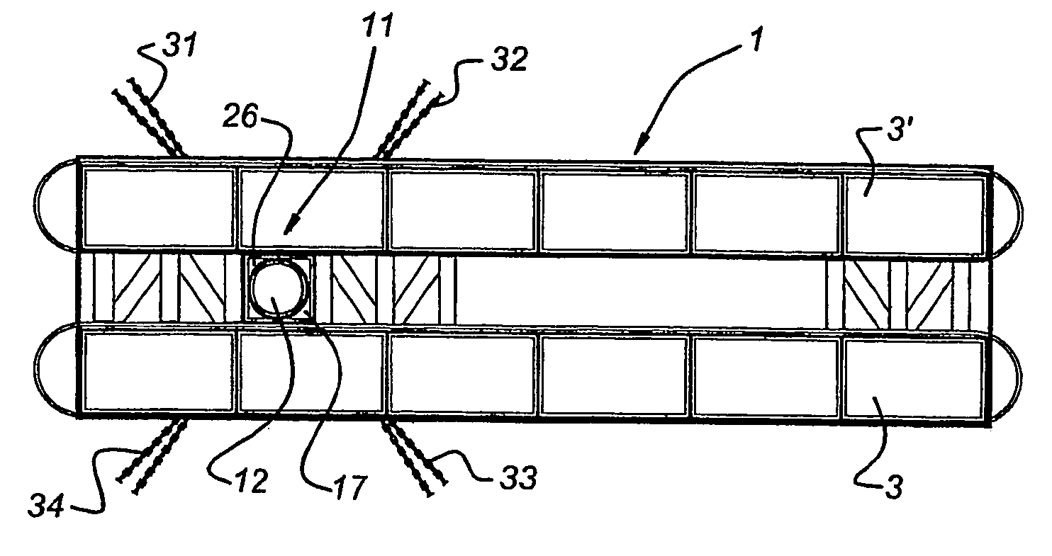
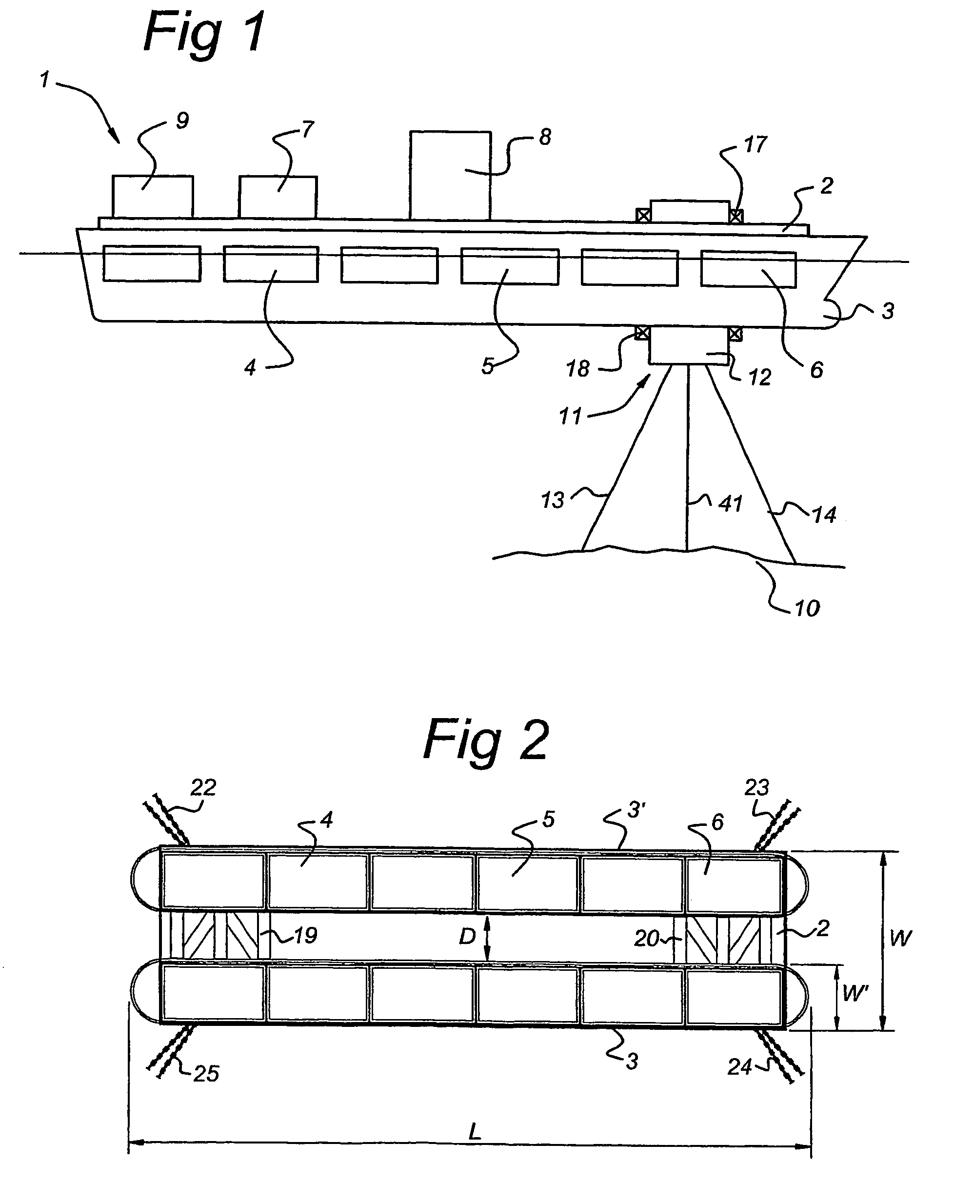
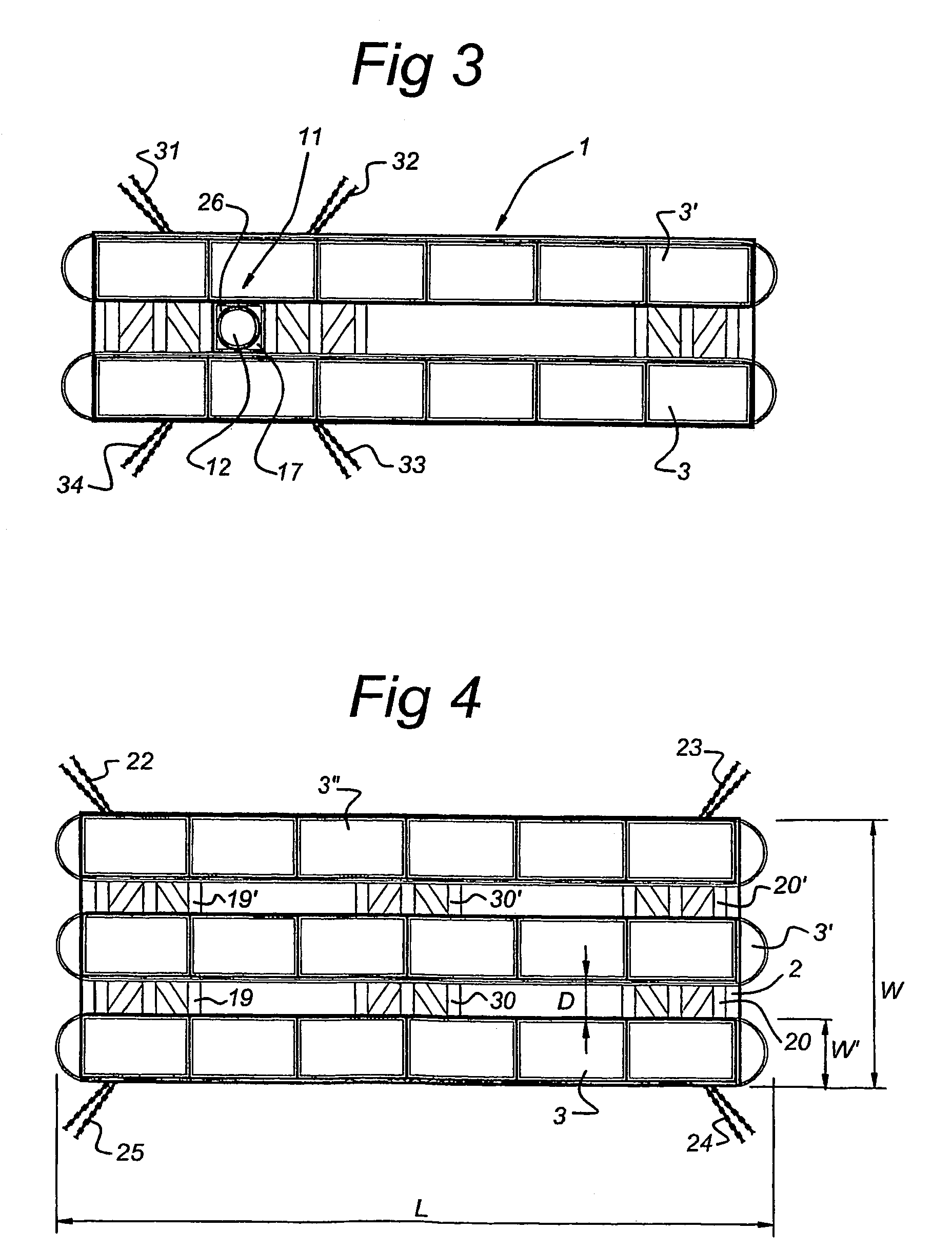
[0026]FIG. 1 shows a vessel 1 in a side view having a deck structure 2 extending over two parallel hulls of which hull 3 is shown in FIG. 1. The hull 3 comprises a row of storage tanks 4, 5, 6. On the deck structure 2, processing equipment 7, 8 is placed as are personnel quarters 9. The vessel 1 is moored to the seabed 10 via a turret 11. The turret 11 comprises a stationary part 12 moored to the seabed 10 via anchor legs 13, 14 and product risers 41, connected to the deck structure 2 and to a lower part of the hull 3 via upper bearings 17 and lower bearings 18. It is also possible to replace anchor legs 13, 14 with a spread mooring construction such as shown in FIG. 2, in which anchor lines 22–25 are connected to the hulls or deck structure near the corners of the deck structure, or to use the anchor legs 13, 14 in combination with such a spread mooring configuration.

[0027]FIG. 2 shows a top view of an alternative embodiment of the vessel of the present invention in which only the ...


PUM


Abstract

Disclosed is a vessel comprising at least two parallel hulls at a predetermined mutual distance. A deck structure is supported on the hulls. Fluid storage tanks are placed in the at least two hulls, at least partly below the deck structure. The deck structure carries fluid processing and/or production equipment. The fluid is a hydrocarbon. The ratio of length to width of the vessel being at least 3, preferably at least 4. The length of the vessel being at least 150 m, preferably at least 250 m, more preferably at least 350 m.

Description

BACKGROUND OF THE INVENTION[0001]1. Field of the Invention[0002]The invention relates to a vessel comprising at least two parallel hulls at a predetermined mutual distance, a deck structure supported on said hulls and fluid storage tanks.[0003]2. Description of the Related Art[0004]From U.S. Pat. No. 3,943,872 an LNG carrier is known, having two parallel hulls interconnected by transverse beams on which cargo tanks are supported. The known LNG tanker has a high center of mass and thereby a reduced stability. Furthermore, the LNG tanks occupies the majority of available deck space.BRIEF SUMMARY OF THE INVENTION[0005]It is an object of the present invention to provide a vessel with large storage facilities for hydrocarbons, which can be built with standard shipbuilding facilities rather than under offshore standards.[0006]It is a further object of the present invention to provide a barge of large dimension which is very stable and which can support a large number of different applicat...

Claims


Application Information

Patent Timeline
Patent Type & Authority Patents(United States)
IPC IPC(8): E02D27/38E02B17/08F16L1/12B63B1/10B63B1/12B63B21/50B63B25/08B63B25/12B63B35/28B63B35/44
CPCB63B1/121B63B1/125B63B35/44B63B25/12B63B21/507B63B2035/448B63B2001/128
Inventor BRINKEL, THEODORUS JOHANNES BERNARDUSVAN WIJNGAARDEN, WILLEM CORNELIS
Owner SINGLE BUOY MOORINGS INC
Why Eureka
Try Eureka