Beam formation unit comprising two axicon lenses, and device comprising one such beam formation unit for introducing radiation energy into a workpiece consisting of a weakly-absorbent material

a technology of weakly absorbent material and beam formation unit, which is applied in the direction of glass making apparatus, instruments, lasers, etc., can solve the problems of insufficient energy loss, insufficient beam focus on the surface of the workpiece, and insufficient beam focus

Inactive Publication Date: 2006-09-05
JENOPTIK AUTOMATISIERUNGSTECHN
View PDF17 Cites 22 Cited by
  • Summary
  • Abstract
  • Description
  • Claims
  • Application Information

AI Technical Summary

Benefits of technology

[0015]It is the primary object of the invention to provide a beam-shaping unit which shapes a ring-shaped beam bundle that can be focused in a punctiform manner and that has a radiationless central area in which there can be arranged an optical element that will not be affected by a beam bundle coming from a radiation source and penetrating the beam-shaping unit and which therefore does not cause losses.
[0016]It is a further object of the invention to provide an arrangement by which, through the use of a beam-shaping unit that meets the object of the invention, relatively weakly absorbent, extensively transparent materials can be machined by electromagnetic radiation, preferably the radiation of a high-power laser, in such a way that ultimately the total absorption in the material is high and, therefore, the radiation energy is made use of efficiently for the machining process through multiplication of the individual absorbencies, and it is ensured that the radiation energy is introduced into the smallest possible interaction volume (volume of the workpiece over which the radiation is absorbed) in order to achieve high-precision machining, and radiation that is not absorbed is substantially prevented from being coupled back into the radiation source.
[0026]The geometry of the resonator unit can also be modified easily so that it is possible to adapt optimally to the workpiece characteristics, especially to the absorption behavior and the desired machining results. For example, the focal length of the first resonator mirror can be selected in such a way that the bundle coming from the second resonator mirror is focused in the interaction volume again, that is, practically returns into itself. After reflections at the second resonator mirror, the mirror and the focusing mirror, the workpiece is even penetrated a fourth time in a focused manner. When the absorption is not too low (≧20%), the majority of the radiation energy is deposited in the zone to be machined. However, the residual radiation that is not absorbed in the interaction volume could then be coupled back into the radiation source if special steps are not taken. This problem can be solved relatively easily in that a beam decoupling unit that eliminates the returning light practically completely is placed in the beam path between the radiation source and the beam-shaping unit. However, for efficient operation of the beam decoupling unit, the radiation must come from the radiation source in a linearly polarized manner. The beam decoupling unit then functions as follows: first, the linearly polarized beam coming from the radiation source traverses a polarizer which is adjusted for full transmission, i.e., the beam bundle undergoes only minimal losses. The beam is then transformed into a circularly polarized beam by passing through a quarter-wave plate. This transformation is required, or at least useful, for numerous applications because the unwanted directional dependency of the results of machining disappears when circularly polarized radiation is used. The circular polarization is substantially maintained along the further beam path. The returning portion also has this characteristic. It now traverses the beam decoupling unit in the opposite direction with the result that the quarter-wave plate “further rotates” the polarization vector in such a way that linearly polarized light results again from the circularly polarized light, but with a polarization plane that is rotated by 90° relative to the radiated electromagnetic radiation field. However, the polarizer is now in the blocking direction for this radiation, i.e., the beam is prevented from being coupled back into the radiation source.
[0029]2. Since the arrangement according to the invention makes it possible to vary the relative position of the focus and workpiece quickly, it is also possible, for example, to proceed in such a way that the workpiece lies exactly in the focus as the machining of the workpiece commences (with continuously operating radiation source). With sufficient radiation output, the desired sensitive destruction of the material joint, i.e., the starting crack, can be produced. For further machining, in which melting and evaporation are not desirable, the workpiece is moved out of the focus area until optimal intensity conditions for severing by means of a stress crack are achieved.
[0032]Additional novel applications that are only mentioned herein but are not described in more detail are made possible by the arrangement according to the invention. For example, a nonlinear optical crystal can be arranged in the third focus point and used to generate higher harmonics of the original beam. High conversion rates are made possible as a result of the resonator arrangement and the relatively high intensity in this third focus point. In this way, the workpiece could be machined by the fundamental wave of the radiation as well as with a higher harmonic, which can lead to advantageous results.
[0033]The beam-shaping unit according to the invention has been described very thoroughly in connection with a resonator unit according to the invention, in which a first resonator mirror is located in the radiationless central area. Other optical elements can also be arranged in place of this first resonator mirror for other uses of the beam-shaping unit. For example, a deflecting mirror could be arranged at this location. This deflecting mirror need no longer be a semitransparent mirror; rather, the impinging beam can be reflected to the maximum extent by a highly reflective coating. In this way, a plurality of beam bundles can be superimposed without losses.

Problems solved by technology

The introduction of high-output electromagnetic radiation into a workpiece comprising a material which is only weakly absorbent continues to be a central problem in materials processing.
Often, it is not sufficient simply to focus the beam on the surface of the workpiece in order to make truly effective use of the available energy, i.e., to introduce this energy into the workpiece in an optimal manner spatially and quantitatively.
However, the energy loss is extreme.
There is no solution known from the prior art by which the available radiation energy can be absorbed nearly completely in a small interaction volume of a partially transparent workpiece.
Since there is no optical element, including optical films, which completely transmits an unchanged beam in one passage direction and reflects it completely in the other passage direction, energy loss is inevitable.
It is clear to the person skilled in the art that practically any optical element located in a beam path will always result in losses, even if these losses are minor.
There is a high loss whenever the element is at times reflective and at times transmissive for radiation coming from different directions as, for example, in a semitransparent mirror or a splitter cube.

Method used


Image

  • Beam formation unit comprising two axicon lenses, and device comprising one such beam formation unit for introducing radiation energy into a workpiece consisting of a weakly-absorbent material
  • Beam formation unit comprising two axicon lenses, and device comprising one such beam formation unit for introducing radiation energy into a workpiece consisting of a weakly-absorbent material
  • Beam formation unit comprising two axicon lenses, and device comprising one such beam formation unit for introducing radiation energy into a workpiece consisting of a weakly-absorbent material

Examples


Embodiment Construction

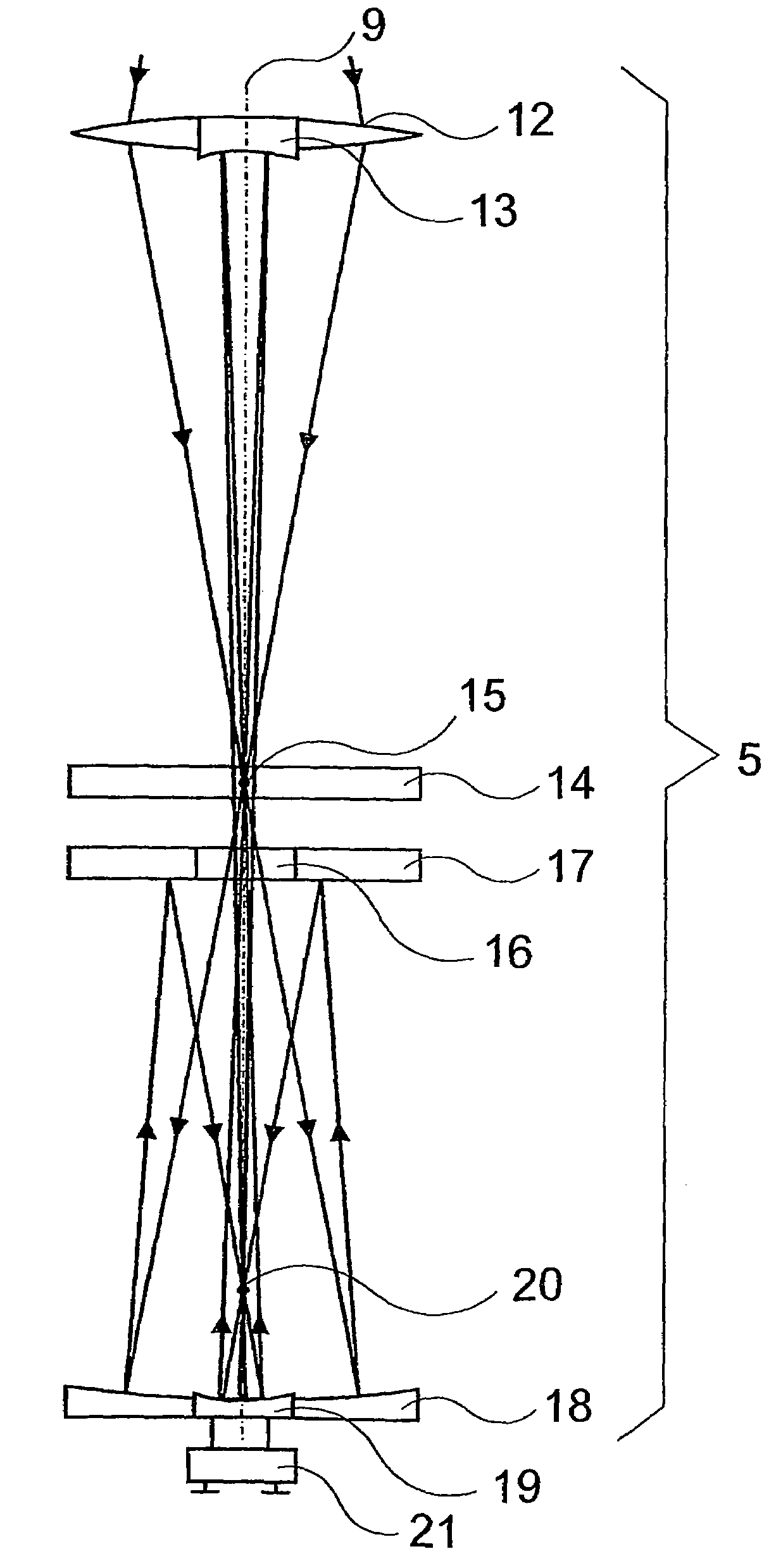
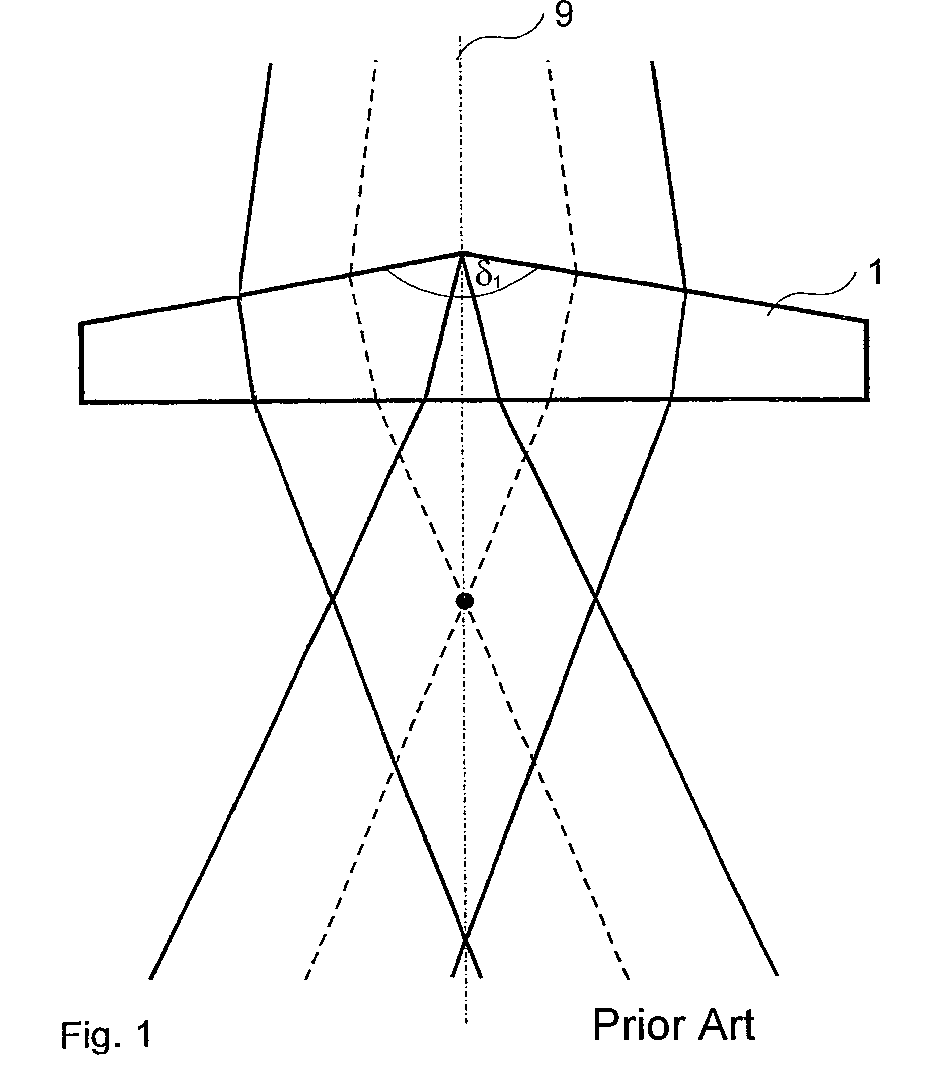
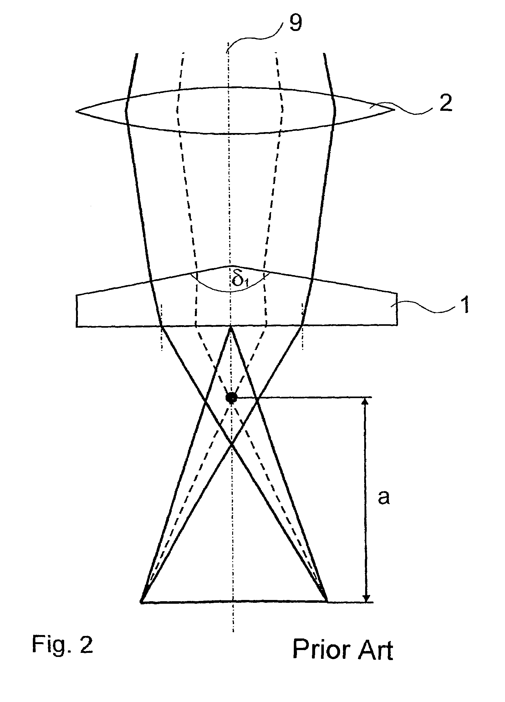
[0044]An arrangement according to the invention substantially comprises a radiation source 6, a beam-shaping unit 4 and a resonator unit 5. The two axicons that are used in the beam-shaping unit 4 take on a central function. Therefore, to facilitate understanding of the invention, FIG. 1 first illustrates the basic function of an individual axicon 1 which is characterized by the cone angle δ. The incident beam bundle, which is assumed to be slightly divergent and symmetric with respect to rotation, e.g., with a Gaussian or rectangular (top-hat) intensity cross section, impinges on the beam-shaping side (conical surface) of the first axicon 1 orthogonally and so as to be exactly centered. As a result of the refraction at its conical surface, the beam exits the first axicon 1 as a divergent ring. The central beams (shown as a dashed line) intersect at a point lying on the optical axis 9 (shown as a dash-dot line); the symmetry of the beam bundle with respect to rotation must always be...


PUM

PropertyMeasurementUnit
diameteraaaaaaaaaa
radiation energyaaaaaaaaaa
reflectionaaaaaaaaaa

Abstract

The invention is directed to a beam-shaping unit for generating a beam bundle which is focused in a punctiform manner, propagates in a ring shape, and has a radiationless central area, comprising a focusing lens, a first axicon and a second axicon, and to an arrangement with a beam-shaping unit of this kind for introducing radiation energy into a workpiece comprising weakly absorbent material which is arranged between a first resonator mirror and a second resonator mirror. The first resonator mirror which is arranged in front of the workpiece in the radiating direction is located in the radiationless central area. The radiation energy can be absorbed to the maximum extent by repeatedly passing through the same interaction volume in the workpiece.

Description

CROSS-REFERENCE TO RELATED APPLICATIONS[0001]This application claims priority of International Application No. PCT / DE2003 / 002853, filed Aug. 25, 2003, and German Application No. 102 40 033.4, filed Aug. 28, 2002, the complete disclosures of which are hereby incorporated by reference.FIELD OF THE INVENTION[0002]The invention is directed to a beam-shaping unit of the generic type known to the person skilled in the art for focusing a beam bundle and to an arrangement of the generic type known from JP 10 244 386 A.DESCRIPTION OF THE RELATED ART[0003]The introduction of high-output electromagnetic radiation into a workpiece comprising a material which is only weakly absorbent continues to be a central problem in materials processing. In this connection, laser materials processing in particular assumes a central role in corresponding developments, since there is a series of suitable radiation sources available with characteristics that can be efficiently adapted to a broad range of applic...

Claims


Application Information

Patent Timeline
Patent Type & Authority Patents(United States)
IPC IPC(8): B23K26/00B23K26/06B23K26/067B23K26/073B23K26/40C03B33/04C03B33/09
CPCB23K26/0604B23K26/0608B23K26/067B23K26/0734B23K26/0652C03B33/091C03B33/093B23K26/0057B23K26/0648C03B33/04B23K2201/36B23K26/53B23K2101/36H01S3/10
Inventor ACKER, STEFANWEISSER, JUERGENSTAUPENDAHL, GISBERT
Owner JENOPTIK AUTOMATISIERUNGSTECHN
Why Eureka
Try Eureka