Method for adjusting the frequency of a MEMS resonator

a technology of mems resonators and frequency adjustment, which is applied in the direction of resistance/reactance/impedence, instruments, measurement devices, etc., can solve the problems of large variations of the resonance frequency of such resonators, significant impact on the operation and/or function of the structure, and difficult to precisely predict, compensate, address and/or predetermine before fabrication

Active Publication Date: 2006-09-05
ROBERT BOSCH GMBH
View PDF201 Cites 64 Cited by
  • Summary
  • Abstract
  • Description
  • Claims
  • Application Information

AI Technical Summary

Problems solved by technology

However, manufacturing and material tolerances regarding such micromechanical structures often significantly impact the operation and / or function of the structure.
In this regard, manufacturing and material tolerances tend to lead to large variations of the resonance frequency of such resonators.
Similarly, the tolerance / range of the material's characteristics and / or properties produce differences in Young's modulus, which are difficult to exactly predict, compensate, address and / or predetermine before fabrication.
Such manufacturing and material tolerances may lead to relative large frequency variations even between identically designed resonators.
Indeed, such frequency variations may be measurable (and likely unacceptable) even between microelectromechanical resonators that undergo identical processing / fabrication, for example, resonators fabricated on the same wafer.
Such a configuration, and, in particular, the glass wafer packaging and sacrificial metal layer, may, among other things, adversely impact the vacuum of the microelectromechanical resonator, particularly in view of the evaporation of the metal material within the resonator chamber.
Such evaporation may produce unwanted contaminants within the chamber which, in turn, may adversely impact the operation of the resonator.

Method used


Image

  • Method for adjusting the frequency of a MEMS resonator
  • Method for adjusting the frequency of a MEMS resonator
  • Method for adjusting the frequency of a MEMS resonator

Examples


Embodiment Construction

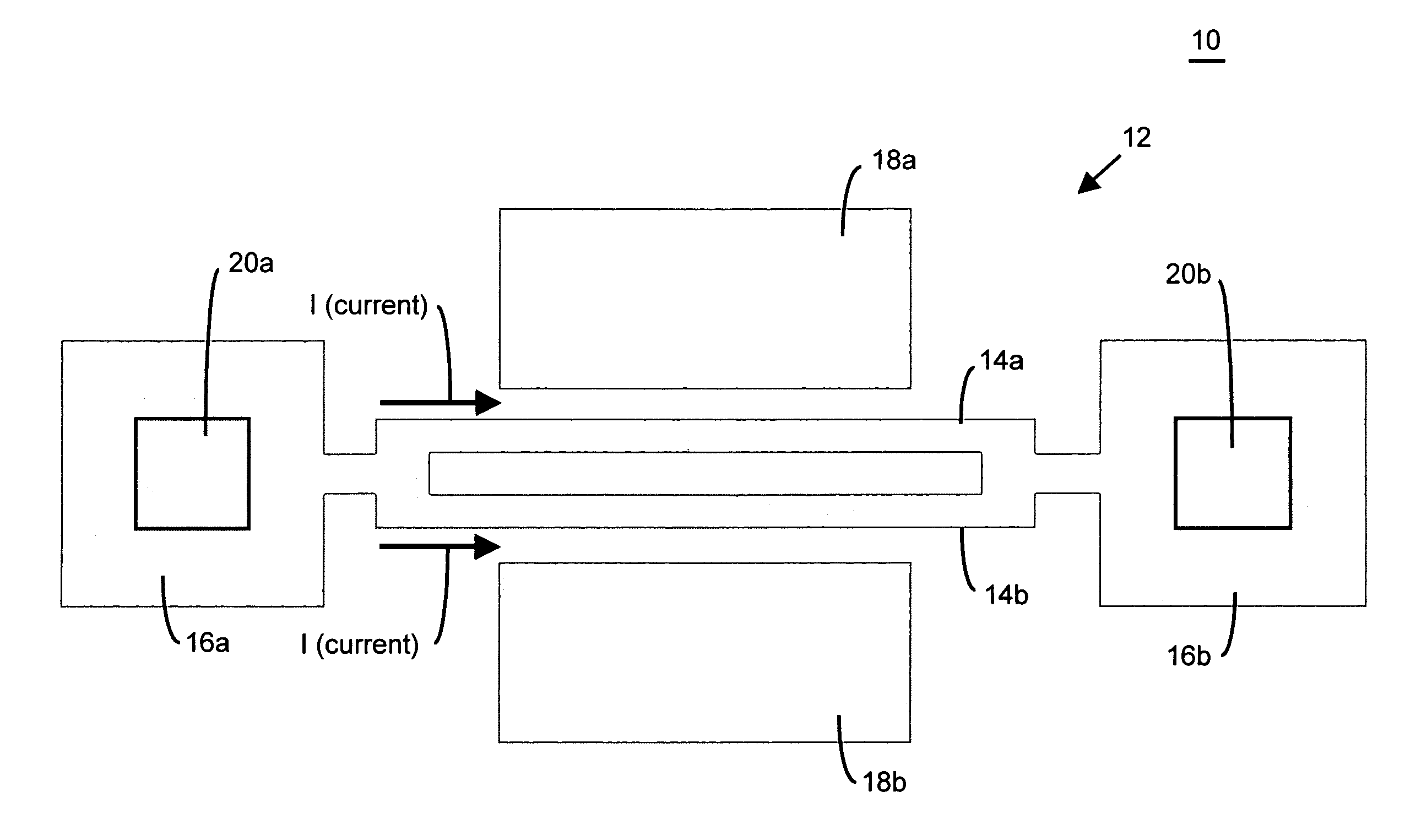
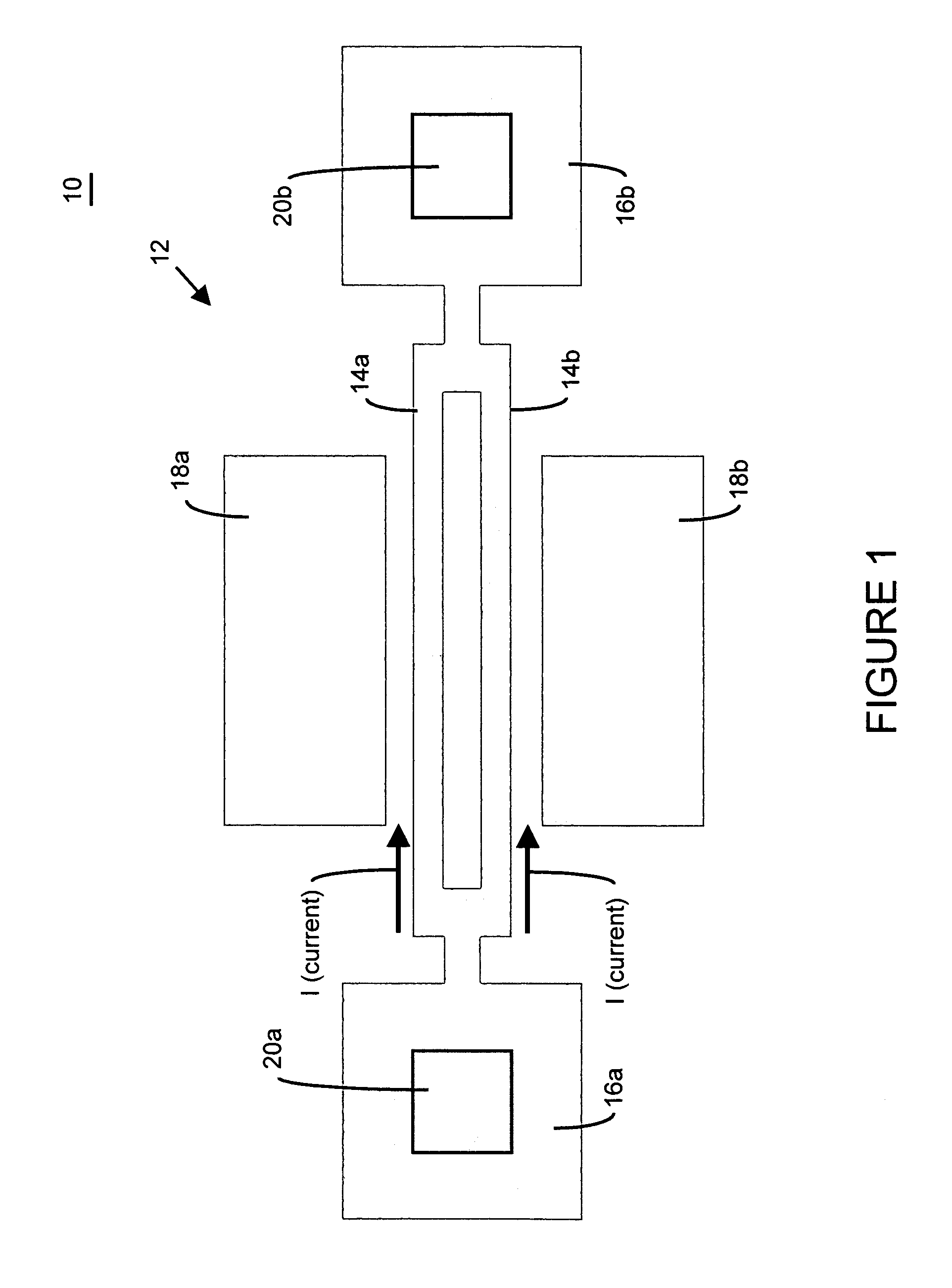
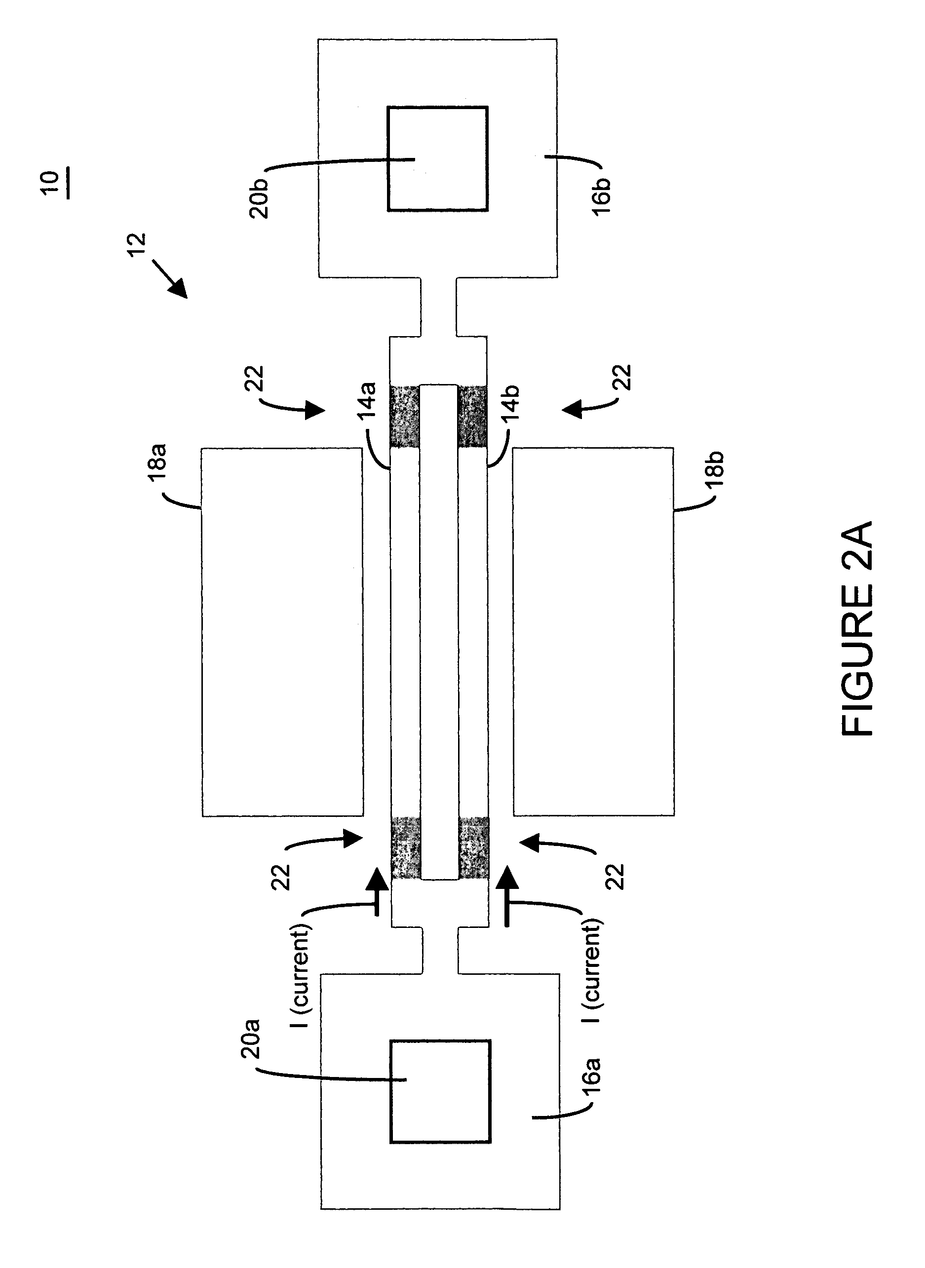
[0039]There are many inventions described and illustrated herein. These inventions are directed to a method of fabricating a microelectromechanical resonator having an output frequency that may be adjusted, tuned, set, defined and / or selected whether before and / or after final packaging. In a first aspect, the method of the present invention adjusts, tunes, sets, defines and / or selects the frequency of the microelectromechanical resonator by changing and / or removing material from the mechanical structure of the resonator by resistively heating one or more elements and / or beams of the mechanical structure (for example, the moveable or expandable electrodes).

[0040]In this aspect of the present invention, an electrical current is applied to the moveable electrodes to resistively heat the electrode to a sufficient temperature so as to change and / or remove material from one or more moveable electrodes of the mechanical structure. In one embodiment, the material may be changed and / or remov...


PUM


Abstract

There are many inventions described and illustrated herein. These inventions are directed to a method of fabricating a microelectromechanical resonator having an output frequency that may be adjusted, tuned, set, defined and / or selected whether before and / or after final packaging. In one aspect, the method of the present invention adjusts, tunes, sets, defines and / or selects the frequency of the microelectromechanical resonator by changing and / or removing material from the mechanical structure of the resonator by resistively heating (in a selective or non-selective manner) one or more elements and / or beams of the mechanical structure (for example, the moveable or expandable electrodes and / or frequency adjustment structures).

Description

BACKGROUND[0001]This invention relates to microelectromechanical systems and / or nanoelectromechanical systems (collectively hereinafter “microelectromechanical systems”) and techniques for fabricating microelectromechanical systems; and, more particularly, in one aspect, for adjusting, tune, setting, defining and / or selecting the output frequency of microelectromechanical resonators.[0002]Many conventional micromechanical structures are based on the reaction (for example, oscillation, deflection or torsion) of a beam structure to an applied force. Such beam structures are often fabricated from monocrystalline or polycrystalline semiconductors. These materials have excellent mechanical strength and a high intrinsic quality factor.[0003]However, manufacturing and material tolerances regarding such micromechanical structures often significantly impact the operation and / or function of the structure. For example, microelectromechanical resonators typically rely upon the bending beam and ...

Claims


Application Information

Patent Timeline
Patent Type & Authority Patents(United States)
IPC IPC(8): H03H3/013H03H9/46H03H3/007H03H9/02H03H9/21H03H9/24
CPCH03H3/0077H03H9/02401H03H9/2473H03H2009/02527H03H2009/02496H03H2009/02511
Inventor LUTZ, MARKUSPARTRIDGE, AARON
Owner ROBERT BOSCH GMBH
Why Eureka
Try Eureka