Systems and methods for sculpting virtual objects in a haptic virtual reality environment
a virtual reality environment and virtual object technology, applied in the field of systems and methods for sculpting virtual objects in a haptic virtual reality environment, can solve the problems of difficulty or inability to recover from mistakes or return to a previous stage of design, and the typical difficulty of using the cad system, and achieve the effect of ease and expressiveness
- Summary
- Abstract
- Description
- Claims
- Application Information
AI Technical Summary
Benefits of technology
Problems solved by technology
Method used
Image
Examples
case 1
of Tool in Empty Space
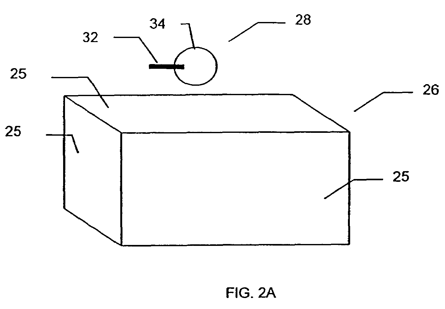
[0110]FIGS. 7A–7C depicts flowcharts of the haptic rendering process 16 which calculates interactions between the virtual object 26 and the virtual tool 28 for one embodiment of the invention. These flowcharts represent movement of the virtual tool 28 in steps relative to the virtual surface 25 of a virtual object 26. First, the haptic rendering process 16 proposes to move the virtual tool origin 27 toward the haptic interface location 98 (step 120). Then the haptic rendering process 16 determines if any of the tool 28 points would penetrate the virtual surface 25 (step 122). If none of the tool 28 points would penetrate the virtual surface 25, this represents “Case 1.” The virtual tool 28 would encounter only empty space by moving to the proposed new location, so the incremental movement of the virtual tool origin 27 is allowed (step 121) and the haptic rendering process 16 returns to step 120.
case 2
of Tool Penetrating the Virtual Surface
[0111]If at the proposed tool position, some points of the virtual tool 28 would penetrate the virtual surface 25 (step 122), then the haptic rendering process 16 finds the direction of shortest distance to the virtual surface as indicated by surface direction vector 101 for the point of the greatest potential penetration into the virtual object 26 by the virtual tool 28 (step 126, see also FIGS. 5B and 5C). The haptic rendering process 16 then calculates a constraint plane or plane of tangency 104 (see FIG. 5D) based on the surface direction vector 101 (step 127 of FIG. 7A). The plane of tangency 104 is a plane orthogonal to the surface direction vector 101. The haptic rendering process 16 then attempts to move the virtual tool origin 27 toward the haptic interface location 98 but constrains the movement to the plane of tangency 104 (step 130) to arrive at a second proposed virtual tool 28 location.
[0112]If none of the tool 28 points would pen...
case 3
of Tool Encountering Edge Condition
[0113]If at the second proposed tool position, some points of the virtual tool 28 would penetrate the virtual surface 25 (step 132), then the haptic rendering process 16 finds the two surface direction vectors 181a and 181b of the virtual object 26 at the tool's 28 two points of greatest penetration at each of the previous two proposed tool positions (step 136). FIG. 8A illustrates a virtual tool 28 encountering the outside or convex edge 177 of a virtual object 26 in one embodiment of the invention. The virtual object 26 extends out of the plane of the diagram, and has an edge 177 that likewise extends out of the plane of the diagram. In FIG. 8B the proposed tool position penetrates the virtual object 26 at point S41 and the haptic rendering process 16 calculates a surface direction vector 181a relative to virtual surface 25a. In FIG. 8C, the haptic rendering process 16 proposes a second proposed tool location based on the surface direction vector...
PUM
 Abstract
Description
Claims
Application Information
 - R&D
- Intellectual Property
- Life Sciences
- Materials
- Tech Scout
- Unparalleled Data Quality
- Higher Quality Content
- 60% Fewer Hallucinations
Browse by: Latest US Patents, China's latest patents, Technical Efficacy Thesaurus, Application Domain, Technology Topic, Popular Technical Reports.
© 2025 PatSnap. All rights reserved.Legal|Privacy policy|Modern Slavery Act Transparency Statement|Sitemap|About US| Contact US: help@patsnap.com


