Systems and methods for creating virtual objects in a sketch mode in a haptic virtual reality environment

Inactive Publication Date: 2005-03-24
3D SYST INC
View PDF98 Cites 141 Cited by
  • Summary
  • Abstract
  • Description
  • Claims
  • Application Information

AI Technical Summary

Benefits of technology

[0009] Thus, there is a need for a 3-D computerized modeling system that overcomes the problems of CAD techniques and traditional noncomputerized modeling techniques. One object of the present invention is to provide a computerized 3-D virt

Problems solved by technology

CAD systems are typically difficult to use and lack the freedom and expressiveness of traditional noncomputerized drawing, sketching, and model-making procedures.
These approaches suffer from traditional limitations such as the time needed to hand design templates, and the difficulty or inability to recover from mistakes or return to a previous stage of design.
Objects created using traditional physical modeling methods cannot be directly incorporated or used in mo

Method used


Image

  • Systems and methods for creating virtual objects in a sketch mode in a haptic virtual reality environment
  • Systems and methods for creating virtual objects in a sketch mode in a haptic virtual reality environment
  • Systems and methods for creating virtual objects in a sketch mode in a haptic virtual reality environment

Examples


case 1

[0129] Case 1 of Tool in Empty Space

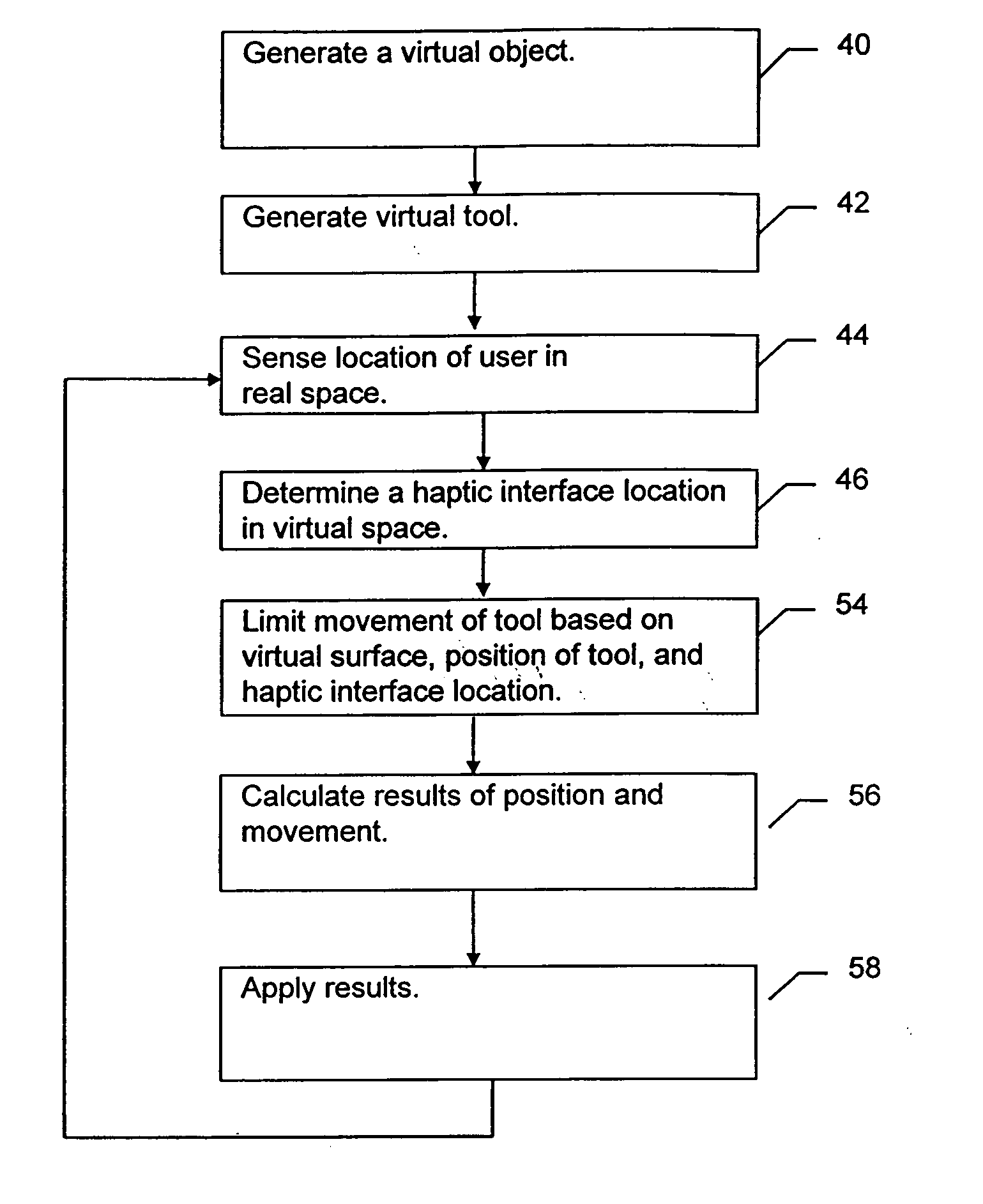
[0130]FIGS. 7A-7C depicts flowcharts of the haptic rendering process 16 which calculates interactions between the virtual object 26 and the virtual tool 28 for one embodiment of the invention. These flowcharts represent movement of the virtual tool 28 in steps relative to the virtual surface 25 of a virtual object 26. First, the haptic rendering process 16 proposes to move the virtual tool origin 27 toward the haptic interface location 98 (step 120). Then the haptic rendering process 16 determines if any of the tool 28 points would penetrate the virtual surface 25 (step 122). If none of the tool 28 points would penetrate the virtual surface 25, this represents “Case 1.” The virtual tool 28 would encounter only empty space by moving to the proposed new location, so the incremental movement of the virtual tool origin 27 is allowed (step 121) and the haptic rendering process 16 returns to step 120.

case 2

[0131] Case 2 of Tool Penetrating the Virtual Surface

[0132] If at the proposed tool position, some points of the virtual tool 28 would penetrate the virtual surface 25 (step 122), then the haptic rendering process 16 finds the direction of shortest distance to the virtual surface as indicated by surface direction vector 101 for the point of the greatest potential penetration into the virtual object 26 by the virtual tool 28 (step 126, see also FIGS. 5B and 5C). The haptic rendering process 16 then calculates a constraint plane or plane of tangency 104 (see FIG. 5D) based on the surface direction vector 101 (step 127 of FIG. 7A). The plane of tangency 104 is a plane orthogonal to the surface direction vector 101. The haptic rendering process 16 then attempts to move the virtual tool origin 27 toward the haptic interface location 98 but constrains the movement to the plane of tangency 104 (step 130) to arrive at a second proposed virtual tool 28 location.

[0133] If none of the tool 28...

case 3

[0134] Case 3 of Tool Encountering Edge Condition

[0135] If at the second proposed tool position, some points of the virtual tool 28 would penetrate the virtual surface 25 (step 132), then the haptic rendering process 16 finds the two surface direction vectors 181a and 181b of the virtual object 26 at the tool's 28 two points of greatest penetration at each of the previous two proposed tool positions (step 136). FIG. 8A illustrates a virtual tool 28 encountering the outside or convex edge 177 of a virtual object 26 in one embodiment of the invention. The virtual object 26 extends out of the plane of the diagram, and has an edge 177 that likewise extends out of the plane of the diagram. In FIG. 8B the proposed tool position penetrates the virtual object 26 at point S41 and the haptic rendering process 16 calculates a surface direction vector 181a relative to virtual surface 25a. In FIG. 8C, the haptic rendering process 16 proposes a second proposed tool location based on the surface d...


PUM


Abstract

A user of a modeling application modifies an initial virtual object using a sketch drawn on one or more construction planes. Typically, construction planes are connected by an axis that intersects the virtual object. The user can draw a sketch on each construction plane, and the modeling application interpolates a shape along the axis between the sketches to determine what material in the virtual object is to be removed from it. In this manner, material may be removed to create a recess or hole in the virtual object or otherwise to slice away material from the object. A user can use two or more axes and construction planes to produce complex shapes from the initial virtual object. A user can also select a portion of a virtual object and mirror the selected portion. Modifications that the user makes in the selected portion are made correspondingly in the mirrored portion.

Description

CROSS-REFERENCE TO RELATED APPLICATION [0001] This application is a continuation-in-part of U.S. patent application Ser. No. ______ (not yet assigned) filed Jun. 28, 1999, entitled “Systems and Methods for Interacting with Virtual Objects in a Haptic Virtual Environment,” and is based on and claims priority to U.S. Provisional Patent Application Ser. No. 60 / 093,304, filed Jul. 17, 1998, entitled “Method and Apparatus for Sculpting Virtual Objects in a Haptic Virtual Reality Environment,” the entire contents of which are incorporated herein by referenceFIELD OF INVENTION [0002] The invention relates generally to a method and apparatus for interacting with virtual objects in a haptic virtual reality environment, and more specifically to a method and apparatus for modifying virtual objects in a haptic virtual reality environment. BACKGROUND OF INVENTION [0003] Computers have been long used to design objects in a computerized environment. Examples are CAD (computer-aided design) systems...

Claims


Application Information

Patent Timeline
IPC IPC(8): G06F3/00G06F3/01G06F3/033G06T19/20
CPCG06F3/016G06F3/0346G06F3/03545G06F2203/013G06T2219/2016G06T19/20G06T2210/21G06T2210/28G06T2200/24B33Y50/00B33Y80/00G06T15/00
Inventor HANDLEY, JOSHUAMIDURA, MARCPAYNE, BRADLEYAVILES, WALTER A.MASSIE, THOMAS H.SHANNON, WALTER C. III
Owner 3D SYST INC
Why Eureka
Try Eureka