Engine loader and transporter apparatus and methods

a technology of aircraft engines and loaders, applied in the direction of machines/engines, manufacturing tools, other domestic objects, etc., can solve the problems of large time and labor costs, complex installation process, and significant challenge in the handling of aircraft engines, so as to reduce time, labor and expense

Inactive Publication Date: 2006-09-12
THE BOEING CO
View PDF24 Cites 38 Cited by
  • Summary
  • Abstract
  • Description
  • Claims
  • Application Information

AI Technical Summary

Benefits of technology

[0006]The present invention is directed to apparatus and methods for transporting and loading aircraft engines. Embodiments of apparatus and methods in accordance with the present invention may advantageously reduce the time, labor, and expense associated with conventional aircraft engine handling apparatus and methods.

Problems solved by technology

Throughout the aviation industry, the handling of aircraft engines presents a significant challenge.
Thus, the need to remove, transport, and install aircraft engines presents a significant challenge in a wide variety of applications.
The installation (and removal) process is typically very complex, and usually involves precise positioning of the engine with respect to the airframe.
This may undesirably necessitate lifting of the aircraft in order to provide enough space between the aircraft engine and the floor or other supporting surface for the engine handling apparatus to operate.
Such upwardly projecting support members may undesirably interfere with nearby portions of the airframe, such as the engine nacelle or thrust reverse assembly.
Due to the size, weight, and complexity of modem aircraft engines, such conventional engine handling apparatus obviously involve an undesirable amount of handling and transferring of the aircraft engine.

Method used


Image

  • Engine loader and transporter apparatus and methods
  • Engine loader and transporter apparatus and methods
  • Engine loader and transporter apparatus and methods

Examples


Embodiment Construction

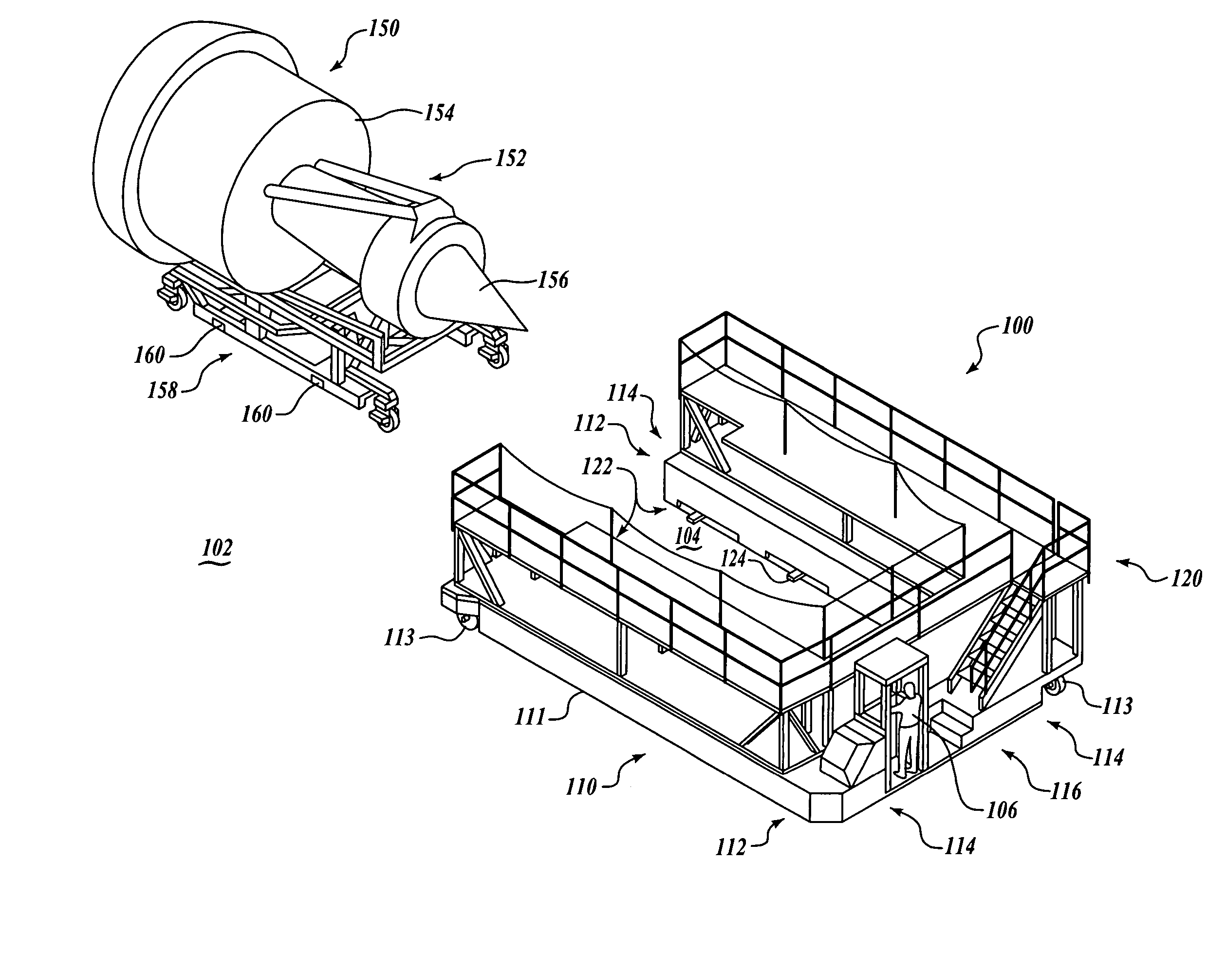
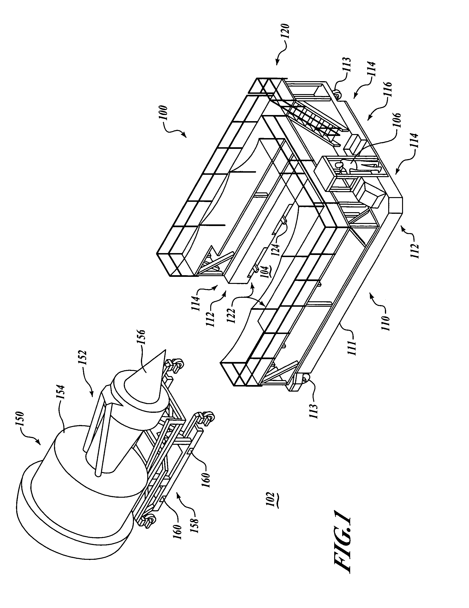
[0023]The present invention relates to apparatus and methods for loading and transporting aircraft engines. Many specific details of certain embodiments of the invention are set forth in the following description and in FIGS. 1–14 to provide a thorough understanding of such embodiments. One skilled in the art, however, will understand that the present invention may have additional embodiments, or that the present invention may be practiced without several of the details described in the following description.

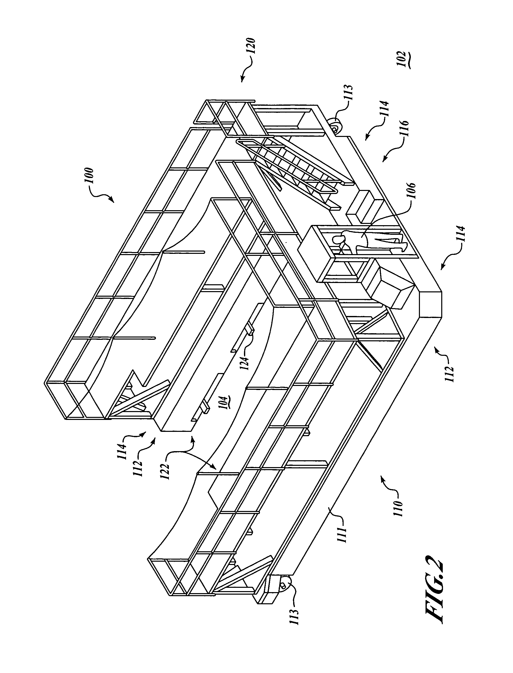
[0024]FIG. 1 is an isometric view of an engine loader and transport assembly 100 in accordance with an embodiment of the present invention. In FIG. 1, the engine loader and transport assembly 100 is shown disengaged from an aircraft engine assembly 150. FIGS. 2 and 3 are rearward and forward isometric views, respectively, of the engine loader and transport assembly 100 of FIG. 1. As shown in FIGS. 1–3, the engine loader and transport assembly 100 includes a drive assembly 110 th...


PUM

PropertyMeasurementUnit
sizeaaaaaaaaaa
weightaaaaaaaaaa
diameteraaaaaaaaaa

Abstract

Engine loader and transporter apparatus and methods are disclosed. In one embodiment, an engine handling assembly includes a motorized drive assembly engageable with a floor surface, and an engagement unit positioned proximate the drive assembly and partially surrounding a working space. The engagement unit includes a pair of coupling assemblies positioned on opposing lateral sides of the working space that are adapted to be selectively coupleable to the aircraft engine assembly when the aircraft engine assembly is positioned at least partially within the working space. A lifting assembly is operatively coupled to the drive assembly and to the engagement unit and is operable to selectively raise and lower the engagement unit and the aircraft engine assembly with respect to the floor surface.

Description

FIELD OF THE INVENTION[0001]The present disclosure relates to apparatus and methods for handling aircraft engines, and more specifically, to engine loader and transporter apparatus and methods.BACKGROUND OF THE INVENTION[0002]Throughout the aviation industry, the handling of aircraft engines presents a significant challenge. For example, during manufacturing of large commercial aircraft, aircraft engines weighing in excess of 20,000 pounds must be positioned precisely with respect to the aircraft airframe during the attachment process. Similarly, aircraft engines must be periodically removed for servicing and maintenance by airlines, aircraft service providers, and various military organizations. Thus, the need to remove, transport, and install aircraft engines presents a significant challenge in a wide variety of applications.[0003]Typically, an engine is installed by lifting the engine upwardly into position and securing it to a portion of an airframe, such as a wing, a wing pylon...

Claims


Application Information

Patent Timeline
Patent Type & Authority Patents(United States)
IPC IPC(8): B66B9/16B60P1/44B60P1/64B66B9/187B21K21/16B23P17/04
CPCB64F5/0036F01D25/285F05D2230/68F05D2230/72Y10T29/49904Y10T29/53974Y10T29/49902Y10T29/53435Y10T29/49716Y10T29/49895Y10T29/53961B64F5/50
Inventor APPLETON, JOSEPH A.BUSCH, TIMOTHY J.BLACK, KEITH E.WESCOTT, KEVIN P.
Owner THE BOEING CO
Why Eureka
Try Eureka