Open hole anchor and associated method

a technology of anchorage and open hole, applied in the field of downhole tools, can solve problems such as cement not adhering

Inactive Publication Date: 2006-09-12
WEATHERFORD TECH HLDG LLC
View PDF43 Cites 61 Cited by
  • Summary
  • Abstract
  • Description
  • Claims
  • Application Information

AI Technical Summary

Benefits of technology

[0013]In one aspect, the expandable system includes an expandable tubular and a deployment system. The deployment system includes a tubular having a bore therethrough with one or more packers disposed around the tubular. The one or more packers are used to exert radial force against the expandable tubular to anchor the expandable tubular within the wellbore.
[0014]The present invention further relates to a method of using the expandable system. The expandable tubular and the deployment system are temporarily connected during run-in of the expandable system. The one or more packers are deployed and actuated to deform at least a portion of the expandable tubular into frictional contact with the wellbore, thus preventing the expandable system from longitudinal axial or rotational movement within the wellbore. After anchoring the expandable tubular within the wellbore, the connection between the expandable tubular and the deployment system is released. The deployment system is then removed from the wellbore, and an expander tool is employed to expand the remainder of the length of the expandable tubular into the wellbore.
[0015]Another aspect of the present invention involves an expandable system which includes an expandable tubular and a deployment system. The deployment system includes a tubular having a bore therethrough with one or more packers disposed therearound. Also connected to the tubular is an expander tool. The one or more packers are again used to exert radial force against the expandable tubular so that the expandable tubular is anchored within the wellbore.
[0016]In use, the expandable tubular is temporarily connected to the tubular during run-in of the expandable system. After the expandable system is run into the desired depth at which to anchor the expandable system, the one or more packers are actuated to deform at least a portion of the expandable tubular into frictional contact with the wellbore, anchoring the expandable system axially and rotationally. The temporary connection is released so that the expander tool may move axially and / or rotationally within the wellbore to expand the remaining length of the expandable tubular into contact with the wellbore.

Problems solved by technology

However, a problem arises in a cased wellbore when the cement does not adhere to the wellbore properly to provide an effective fluid seal.
The ineffective seal allows water to travel along the cement and wellbore interface to the hydrocarbon rich zone.

Method used


Image

  • Open hole anchor and associated method
  • Open hole anchor and associated method
  • Open hole anchor and associated method

Examples


Embodiment Construction

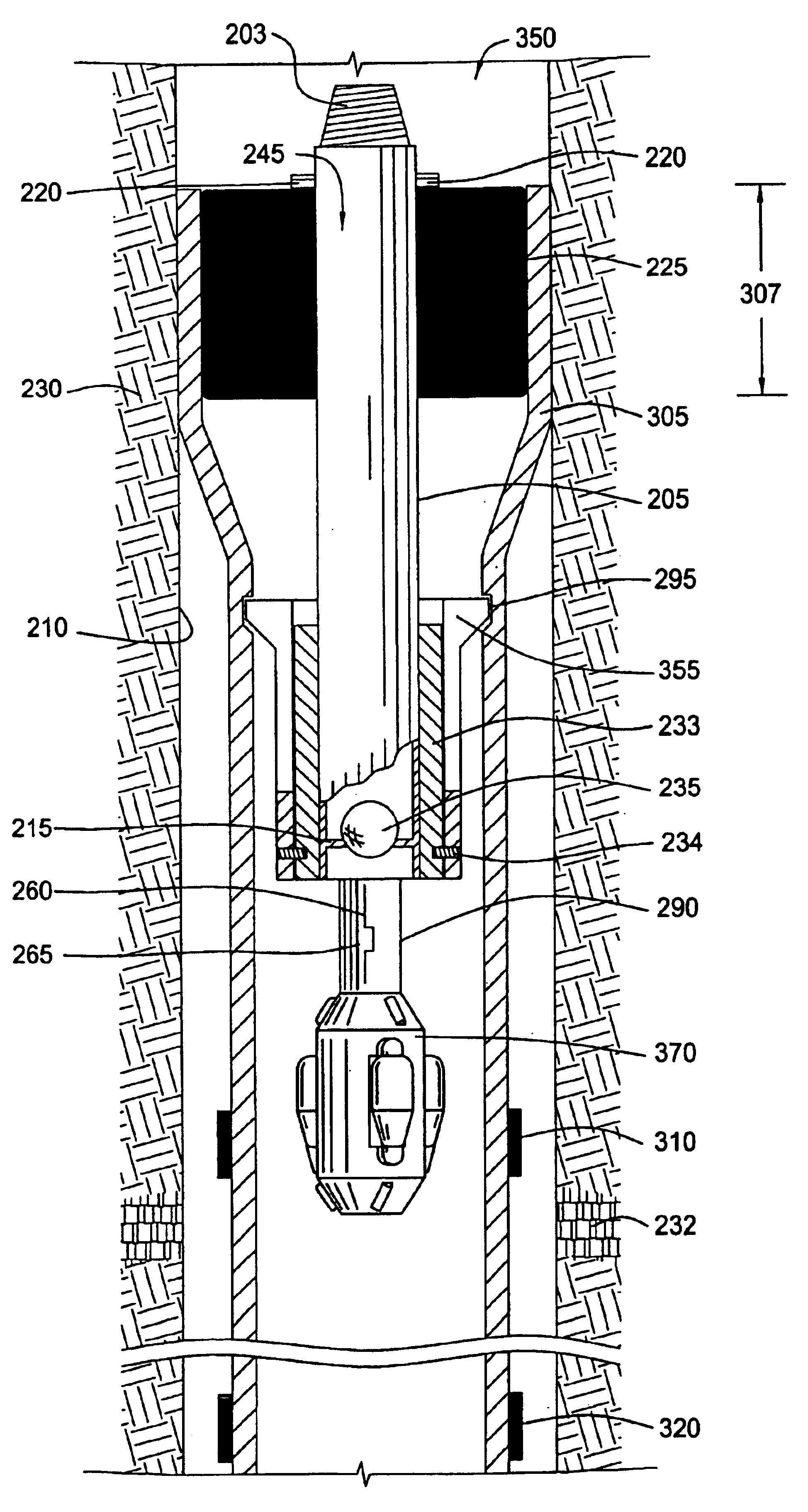
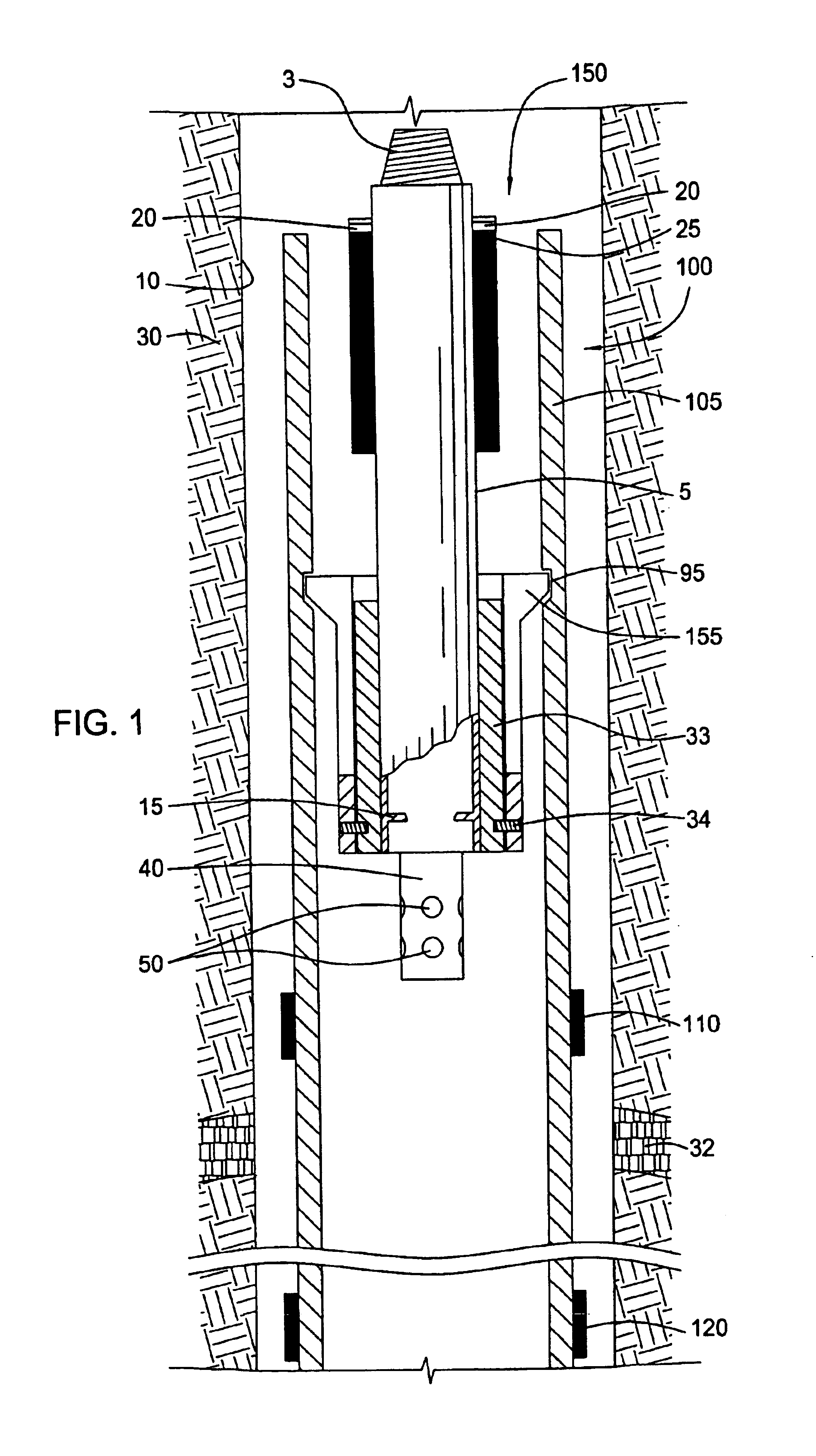
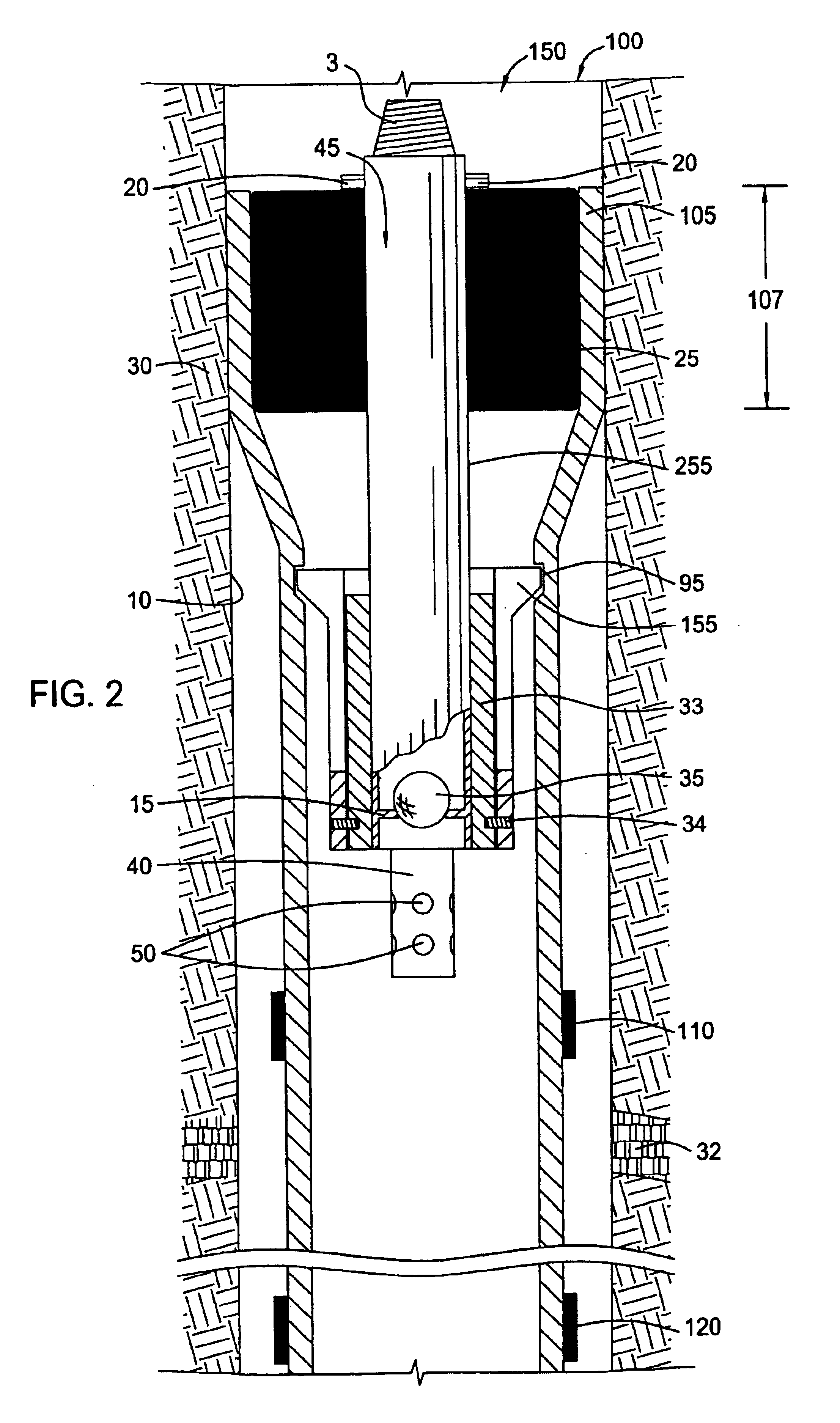
[0034]FIG. 1 shows an expandable system 100 run into an open hole wellbore 10 in the run-in configuration. Aspects of the present invention are not limited to application to an open hole wellbore, but are equally applicable to a cased wellbore or tubular, as well as to horizontal or deviated wellbores. The present invention may be used to shut off production from a formation 30 as well as prevent loss of fluid in the wellbore 10 to the formation 30, along with other purposes for which isolation of an area of interest in a wellbore is productive. The expandable system 100 comprises an expandable tubular 105 and a deployment system 150. The expandable tubular 105 has an upper packer 110 and a lower packer 120 attached thereto which isolate an area of interest in the formation 30 of the wellbore 10. Exemplary expandable packers 110 and 120 which are effective in sealing the annular area between the expanded packer and the wellbore 10, thus isolating the production zone within the wellb...


PUM


Abstract

The present invention relates to a method and apparatus for anchoring an expandable tubular within a wellbore prior to expanding the length of the expandable tubular into contact with the wellbore. An expandable system comprises the expandable tubular and a deployment tool, wherein the deployment tool exerts radial force against the expandable tubular to expand at least a portion of the expandable tubular into contact with the wellbore to anchor the expandable tubular prior to the expansion process. A method for anchoring an expandable tubular within a wellbore prior to the expansion process is also provided, wherein radial force expands the expandable tubular into contact with the wellbore to initially anchor the expandable tubular. A method for altering the shape of the anchor is also provided.

Description

BACKGROUND OF THE INVENTION[0001]1 . Field of the Invention[0002]The present invention generally relates to a downhole tool for use in a wellbore. More particularly, the invention relates to isolating an area of interest within a wellbore. More particularly still, the invention relates to anchoring an expandable tubular within the wellbore prior to isolating the wellbore.[0003]2 . Description of the Related Art[0004]In the drilling of oil and gas wells, a wellbore is formed using a drill bit that is urged downwardly at a lower end of a drill string. After drilling a predetermined depth, the drill string and bit are removed, and the wellbore is typically lined with a string of steel pipe called casing. The casing provides support to the wellbore and facilitates the isolation of certain areas of the wellbore adjacent hydrocarbon bearing formations. The casing typically extends down the wellbore from the surface of the well to a designated depth. An annular area is thus defined between...

Claims


Application Information

Patent Timeline
Patent Type & Authority Patents(United States)
IPC IPC(8): E21B43/10E21B29/00E21B23/01E21B33/127
CPCE21B23/01E21B43/106E21B43/105E21B33/127E21B43/103
Inventor WHANGER, KENHARRALL, SIMONCUFFE, CHRISTOPHERBADRAK, ROBERT
Owner WEATHERFORD TECH HLDG LLC
Why Eureka
Try Eureka