Autonomous satellite docking system

a satellite and autonomous technology, applied in the field of spacecraft docking, can solve the problems of cost of launch and recovery of payloads

Inactive Publication Date: 2006-09-12
MICHIGAN AEROSPACE
View PDF26 Cites 76 Cited by
  • Summary
  • Abstract
  • Description
  • Claims
  • Application Information

AI Technical Summary

Problems solved by technology

A major problem is the costs in launch and recovery of payloads.

Method used


Image

  • Autonomous satellite docking system
  • Autonomous satellite docking system
  • Autonomous satellite docking system

Examples


Embodiment Construction

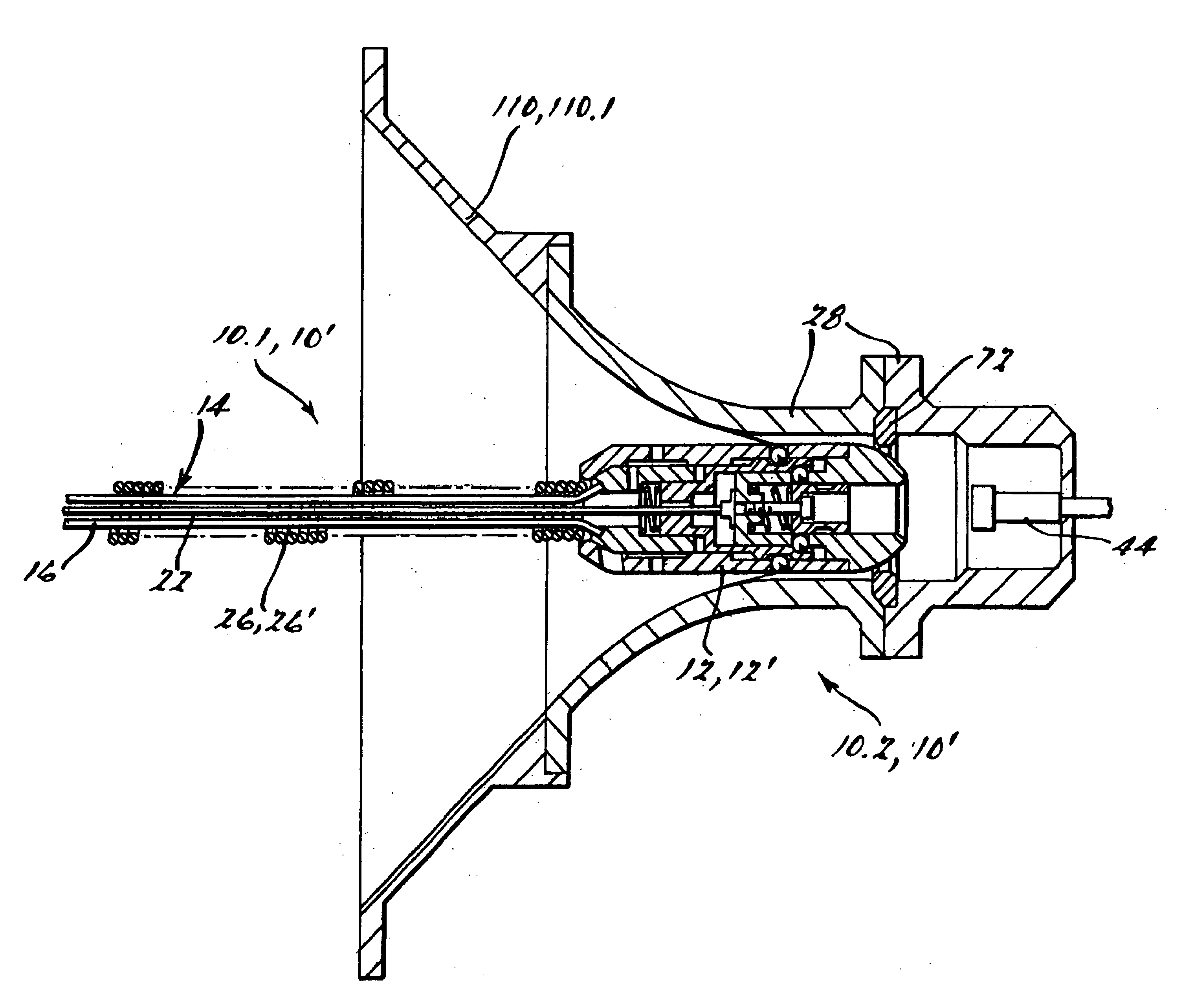
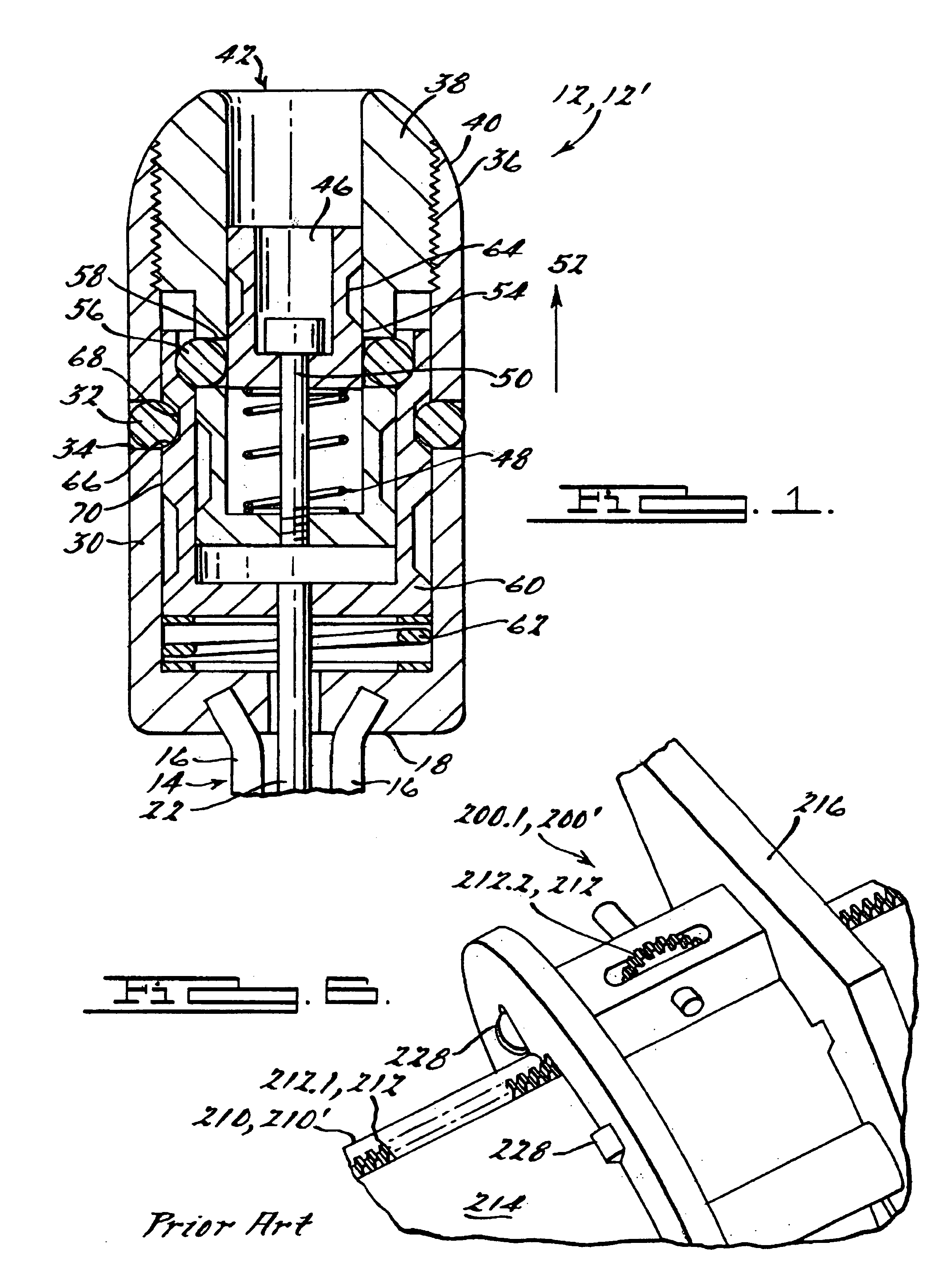
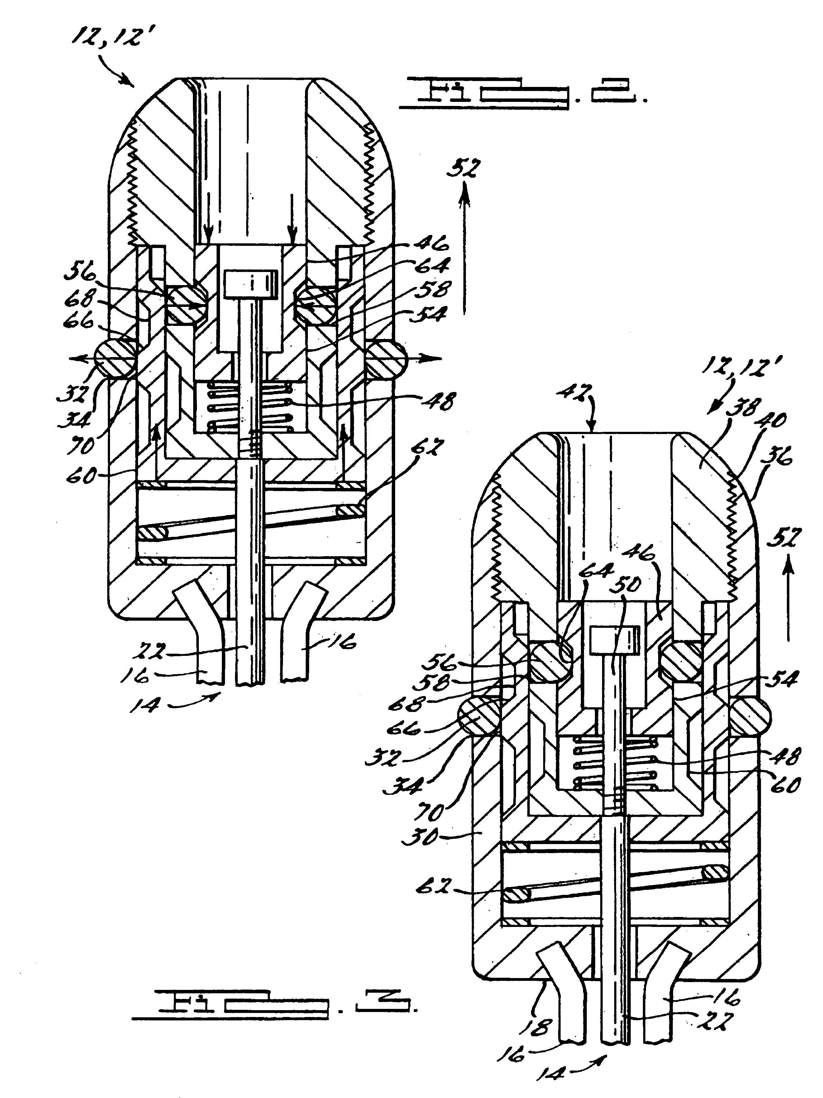
[0029]The invention will now be described in detail with reference to the Figures, using the following definitions:[0030]Chaser 10.1—The half of a docking mechanism 10 that is attached to the satellite that is performing the servicing operation, or chase vehicle 1;[0031]Target 10.2—The half of a docking mechanism 10 that is attached to the satellite that is being serviced, or target vehicle 3;[0032]Soft-Dock—The capture of the target vehicle 3 by the chase vehicle 1 by a method that imparts little or no force on the target vehicle 3. This is in contrast to hard-dock which nominally involves a collision between parts of the chaser 1 and target 3 vehicles. Hard-dock procedures generally impart a great deal of force on the target vehicle 3, which can push it away before the docking mechanism is fully engaged;[0033]Harpoon—The end effector 12 used by the chase vehicle 1 to capture the target vehicle 3;[0034]ARD 100—The autonomous rendezvous and docking mechanism 100 described in U.S. Pa...


PUM


Abstract

This invention solves problems associated with prior-art soft-dock mechanisms by placing all active components of a soft-dock system on the chaser side of the mechanism, leaving the target side of the mechanism completely passive (i.e., requiring no power expenditure or self-actuated moving parts to operate). In particular, the active components are supported on the end of a flexible cable attached to the probe, or chaser, side of the device. These components act as a sort of spring-loaded “trap.” Once the end of the probe passes into a receptacle on the target side, the mechanism is triggered, engaging it in such a way that it can no longer be pulled out of the receptacle until it is reset. The soft-docking cable may be replaced with a rigid, semi-rigid or jointed post that is used to bring a capture mechanism into engagement with its corresponding receptacle or receiving structure. The magnetic end effector may also be implemented as an electro-magnet, which requires power to maintain the holding force, or a permanent magnet, which captures a target without power. The main target cone may be either a metallic cone: or a non-metallic cone constructed of fabric, plastic, or other flexible material.

Description

REFERENCE TO RELATED APPLICATION[0001]This application claims priority from U.S. Provisional Patent Application Ser. No. 60 / 416,138, filed Oct. 4, 2002; and is a continuation-in-part of U.S. patent application Ser. No. 10 / 286,192, filed Nov. 1, 2002, which claims priority from U.S. Provisional Patent Application Ser. No. 60 / 335,563, filed Nov. 1, 2001. The entire content of each application being incorporated herein by reference.[0002]This invention was made with Government support under DAAH01-00-C-R012 and DAAH01-01-C-R015 awarded by the U.S. Army Aviation and Missile Command, with funding from the Defense Advanced Research Projects Agency (DARPA). The Government has certain rights in this invention.FIELD OF THE INVENTION[0003]This invention relates generally to spacecraft docking and, in particular, to a system of the type wherein all active components are disposed on a chase vehicle.BACKGROUND OF THE INVENTION[0004]There is interest in commercial uses of outer space, particularl...

Claims


Application Information

Patent Timeline
Patent Type & Authority Patents(United States)
IPC IPC(8): B64G1/64
CPCB64G1/646
Inventor TCHORYK, PETEPAVLICH, JANEWASSICK, GREGHAYS, ANTHONY B.RITTER, GREG
Owner MICHIGAN AEROSPACE
Why Eureka
Try Eureka